Sunday, June 24, 2012

Transmission Compatibility

One of the purposes of creating this blog is to share the information (and mistakes) learned as the build progresses.  There have been significant EV conversion activity with many different cars, but the BMW brand has not been converted as much as I think that it should be.  What could be better than an Electric Ultimate Driving Machine !!

From what has been learned from available sources, the following BMW models all appear to use the same Getrag transmission.  Should a reader find an error in the table, please contact me and we will research further and change the table to reflect reality.

BMW models that use manual transmission equivalent to 1992 325i.
VIN WBACB3315NFE09631
VIN decoded:  1992, August, E36, Sedan, USA, 325i, Manual, Left Hand
Getrag 5 speed standard transmission / S5D 250G AJT
1993 - 1999 318is 2DR E36
1993 - 1999 318is 4DR E36
1994 - 1999 318is CONV E36
1995 - 1999 318ti HATCH E36
1999 - 2002 320i 4DR E46
1999 - 2000 323Ci 2DR E46
1999 - 2000 323Ci CONV E46
2000 - 2000 323i WAGON E46
1999 - 2000 323i 4DR E46
1996 - 1999 323i 4DR E36
1996 - 1999 323i CONV E36
1996 - 1999 323is 2DR E36
2000 - 2003 325Ci 2DR E46
2000 - 2003 325Ci CONV E46
1992 - 1995 325i 4DR E36
1994 - 1995 325i CONV E36
2000 - 2003 325i 4DR E46
2000 - 2003 325i WAGON E46
1992 - 1995 325is 2DR E36
2000 - 2003 525i 4DR E39
1995 - 2000 Z3 1.9 ROADSTER E36
1997 - 1999 Z3 2.3/2.5 ROADSTER E36
2000 - 2003 Z3 2.5I ROADSTER E36

The following drawing is a CAD generated representation that started with a traced outline, then machinist ruler, then calipers, then data sheets from web sites, and finally countless hours by David Fischer on his computer to create the final drawing.  If the reader is interested in finding an identical transmission to the one being used in this 1992 BMW 325i conversion, then their bell housing should have identical bolt locations to this drawing.  The reference dimension is 138.00 mm between the top 2 bolts.  The CAD drawing outline has been smoothed out a little, and it may be as much as 3 mm larger than the actual transmission outline.  Kinko's or similar print shops can print full size drawings at very low cost, which can then be cut out and compared directly to the face of the bell housing.  Contact the blog by email if you are interested in more details.


CAD Concept drawing of Bell Housing Adapter Plate.  It is uploaded as a jpg file and it is hard to see.  We will investigate how to darken the image.

Tuesday, June 19, 2012

Measuring the "Magic Number"

Measuring the “Magic Number”

Although there have not been any posts recently, in fact a great deal is happening.  The adapter plate remains the primary focus.  Two different suppliers are working on two significantly different designs.  One will use the key way and the other is designed around a tapered hub.  Each process of manufacturing the hub and transmission adapters requires the determination of the precise distance between the face of the flywheel engine flange and the face of the engine block.  This number in the EV parlance has been called “the magic number” for the adapter plate.  This distance must be duplicated in the final design of the adapter.
Picture 4704
Flywheel engine flange after removal of the flywheel and the 19 mm hex bolts.

To obtain the measurement, place a machinist ruler ( in this example a Starrett, 19.5”/500mm, from McMaster Carr #2117A53) against the face of the flywheel engine flange, and then using a caliper (Mitutoyo 6”/150 mm, available from McMaster Carr # 8647A42) positioned perpendicular to the long dimension of the ruler, open the jaws to extend the depth measuring pin.  See picture 4714.


Picture 4714

Showing the orientation of the caliper and the steel machinists ruler.

Then with gentle pressure push the caliper against the engine block.  The pin will withdraw until the base of the caliper is flush and perpendicular to the ruler.  The reading on the caliper at that point, is the distance between the engine housing and the outermost edge of the ruler.  Upon subtraction of the width of the ruler, the difference reflects the distance between the engine block and the face of the flywheel engine flange.


Picture 4716

Close up of the caliper positioned perpendicular to the ruler, with the center depth measuring pin in contact with the previously cleaned engine surface.

In the case the 1992 BMW 325i Getrag transmission, there is also a metal plate (1.0 mm thick) that is situated between the block and the transmission.  The plate appears to close off the open areas of the bell housing when it is attached to the engine block.  This thickness must be subtracted from the above calculation to obtain “the magic number”.

The challenge is to hold the ruler perpendicular to the flange plate, and to hold the caliper depth surface both parallel to the ruler and perpendicular to the engine block.

By the method described here, "the magic number" was determined to be 20.17 mm.


Sunday, June 10, 2012

Systems Battery Master Shut Off

When the battery is connected, various systems on board continue to consume battery power.  To avoid battery drain between sessions, the battery each time has been disconnected at the terminals.  So, a small upgrade today.  The autoparts store had the following on the shelf:

4 gauge, 32” Switch to Starter Battery Cable (Autocraft prt AC136)
4 gauge, 10” Battery Cable to Post to Terminal (SuperStart SK8410R)
Battery Isolation Switch, 300 Amp, for RV, Marine, and Farm equipment (Dorman part # 85988)
Battery Stud to Post Terminal (3/8” thread)
3/8" Bolt and 2 5/16" washers (to secure bottom of Post to Switch/Starter Cable)
The Isolator Switch (with easy to remove red handle)  now allows for the battery to be completely disconnected between sessions and if any circuit is left on accidentally, then the systems battery is now protected.   


Picture DSC04688

Picture showing the Isolation Switch prior to being mounted on metal brackets.  Red cable at bottom left of picture is connected to bottom right.

Saturday, June 2, 2012

Metal Tags

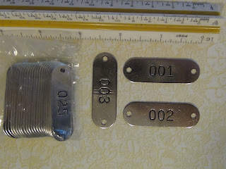
Metal tags (1-25) were obtained from McMaster Carr (http://www.mcmaster.com/#metal-identification-tags/=hswvtd, part # 1090T42). They are made of 304 SS metal with embossed numbering. They can be purchased in packets numbered 1-25, 26-50, 51-75, 76-100, so expansion of the project should not be impeded.   Hopefully, after attaching with plastic tie offs, they should survive power washing and general dirt and still be legible.  The current tape and paper tags have tended to get smudged or be torn or dislodged.  It would have been nice to have the metal tags during the initial demolition.  Every time a connector needed to be separated, a pair of tags could have been attached to each side of the cut point.   No need then to remove gloves, find the pencil, the paper, etc.
 Picture 0961 Plastic tie-offs from Home Depot will complete the attachment.