Thursday, February 23, 2023

Cooling Fans Mounted to Hyper9 Controller Support - 1.0

 To build the controller support, a sheet of 0.063-0.067" 5052-H32  Aluminum measuring 27" x 10.5" was prepared.  


DSC01560 after boring out the fan vents (4.5" diameter) and drilling the 5/32" holes for the mounting bolts, the sheet was bent to shape.  The original motor cradles offered by NetGain have a 15 degree flare, so the bottom mounting surfaces of the support plate were bent 15 degrees (relative to the base) to conform.  Top bends are 90 degrees.  The  Top surface is 10.5" x 11.75" with the sides 6.25" x 10.5".


DSC01562 side view showing the pair of 4.5" vents for the box fans and the 5/32" holes for mounting.


DSC01563 test fitting of the platform with the Hyper9.


DSC01647 showing original controller support version 1.0 o n the left and the newer version 2.0 on the right.  The left side is compatible with a mounting surface that is 15 degrees from the platform, while  the right side is parallel to the mounting surface.     Edited 3/23/23

DSC01645 showing the end on view of the support platform attached to the cradle.


DSC01652 showing the detail of the mounting tabs.  The mounting holes on the left have not yet bee drilled.   Updated 3/23/23


DSC01645 showing the end on view of the support platform attached to the cradle.   Edited 3/23/23


DSC01646 showing Version 2.0 support platform mounted to the cradle.  The bottom bolt is initially tightened to compress the cradle against the motor (or in this case the surrogate PVC motor) and after secure, the internal nut is tightened to secure the support platform to the cradle itself.   Edited 3/23/23


DSC01690 showing the plasma cutting of a support plate from a 0.067" x 48" x 48" 5052-H32  Aluminum sheet.  ($45 from Alro Metals).  A Langmuir Systems - Crossfire Pro (at Bart's Precision Machinery and Fab) was used with a total cutting time of 93 seconds per piece.   Updated 4/9/23


DSC01646 showing Version 2.0 after being cut, but prior to drilling the fan mounting holes, and bending to shape.  


                Heat Sinks Mounted to the Controller Support


DSC01569 showing the maximum length cooling heat sink (11.75" L x 7.25" W x 1.25" D with 1.0" fins) with both fans mounted externally.  The fans do not clear the fins.


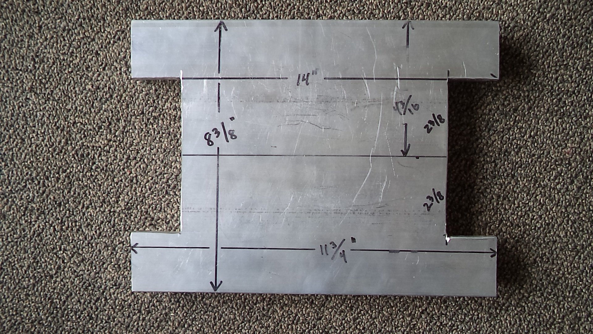
DSC01575 rear face of 11.75" x 8.375" heat sink after removing material to provide for fan clearance.


DSC01574 front face of 11.75" x 8.375" heat sink after removing material to provide for fan clearance.


DSC01619 view from the bottom of the "modified maximum length" heat sink in place.  A wider heat could be used.


A more elegant heatsink was later machined from a second piece in which only the fins were removed in the area of the box fans.   


DSC01571 showing a smaller heat sink (7" L x 8.5" W x 1.25" D with 1.0" fins) which allows for both cooling fans to be located internally without modifying the heat sink (as in DSC01619 above).  Replacement of the fans in this configuration would also be expected to be easier then in the case of  DSC01619.  

Edited 3/24/2023


DSC01639   Closeup of the side of the heatsink shown in DSC01571 above.  The heatsinks are generally not flat and there is a slight curvature.  To obtain a precision contact surface between the heatsink and the controller base, the heatsinks must be machined perfectly flat prior to installation.
.
Edited 3/25/2023


DSC01654 Closeup view of heatsink shown in DSC01571.  The 1.25" x 1.25" x 0.125" Aluminum angle was cut to 9" length and drilled for attachment to the heatsink and the mounting surface.    


DSC01653 Back side surface of heatsink shown in DSC01571 above.  Heatsink base is is 9" x 7.25" and the overall height is about 1.305".  


Motor Surrogate - 8" PVC Pipe

The Hyper9 weighs about 120 pounds and it is a challenge when moving it around the shop.  The Hyper9 extruded Aluminum housing was measured to have an actual diameter of  22.0 cm (8.66 inches) and a body length (from edge of fins to edge of fins with the end caps removed) of 27.0 cm or 10.63 inches.

Standard 8" PVC pipe has an OD of about 8.625".  Bushnell (847-297-4510 at 2110 Oxford Road, Des Plains, Illinois  60018) stocks 5 foot lengths of  8" PVC at $19.52 per foot and we were able to cut several 12" lengths for our own use.  The weight of the surrogate and the pair of cradles is 12.44 pounds (5.65 kg).

DSC01618  showing a Hyper9 PVC surrogate with attached cradle mounts (as shown it weighs 12.44 pounds).  The surrogate can be positioned within the engine compartment using stiff wire or blocks of wood without the danger of dropping a heavy Hyper9.  Estimates can then be made as to how the car's  engine mounts (or frame) can be incorporated into the build.  

Wednesday, February 22, 2023

Hyper9 SME Controller Box - 1


A box measuring 12" (W) x 10.25" (D) x 6" (H) was fabricated using 0.067" 5052 H32 Aluminum.  The corners were welded and two lids were prepared, one solid and one transparent to allow for viewing.


DSC01603 View from the top showing the Aluminum control box with the plastic window installed.  The bus bars will penetrate the left side and a cowling will be added over the terminals to prevent a  shock hazard.  There is plenty of room within the box to include a contactor, main fuse, shut off, USB port (for communication and programming), and support wiring, etc.  High voltage power to B+ and B- will be brought in through the side of the box with shielded cables and a water tight gland.  A 350 amp plug/connector will allow for connection to the test workbench or connection to the battery pack in the car. 


DSC01605 end on view of the control box.


DSC01606 oblique view of the control box.  The lid is secured with eight 4-40 screws that use PEM steel press-fit nuts for sheet metal (McMaster 95185A125 at $12.68 for 50)


DSC01607 closeup of the press fit female steel press-fit nuts that were used to secure the lids to the controller box.  A shop press was used to insert the nuts.  4-40  is probably too small and in the next build a slightly larger bolt and press-fit nut will be used. 

Wiring Options to Connect Hyper9 Controller to the Hyper9 Motor Using A Support


DSC01617 showing one of a pair of box fan covers that were added to the support  (McMaster cat 19155K96, at $1.84 each).  edited 2/23/2023

Use of Copper Bus Bars and Rods - No Brake Press Required

In an effort to decrease the footprint of the power cables, copper bus bars were considered.  One can either bend a series of bars, or use bus bars and 5/8" copper rods (standoffs) that elevate the motor terminals into the plane of the controller terminals.


DSC01595 of the three 5/8" OD copper rods that were drilled and tapped for M10-1.5 with 13 mm depth at the bottom, and M8-1.25 with 13 mm depth at the top.  M10-1.5 x 30  mm stainless steel studs (McMaster 93805A425 at $3.09 each) completed the bottom installation (25 mm length was found to be too short).


DSC01599 showing a mock up of possible bus bars that would be "L" shaped.  Even with the excess copper at the corners trimmed off, the corners extend significantly out to the side and they will be more difficult to enclose later.

Edited 2/28/2023

Purchased a remnant of 0.125" Copper plate that was 2.25 x 24.0" (ALRO Outlet for $25.08 includes $7.00 cut charge.)

Using the Copper Rods and Bus bar design above, cut out a pair of cardboard templates and trial fit them to the motor.  Laid out the templates on the Coper plate to maximize the use of the smooth factory edge (DSC01620)


DSC01620 showing the cardboard templates positioned on the Copper plate prior to bandsaw cutting.


Attached Avery TrueBlock Shipping Label 5165 sheet to Copper plate for ease of marking part outline. 


DSC01621 closeup of the Copper plate after drawing part outline.  Longest length (upper right) positioned to take advantage of the smooth factory edge 


DSC01753 Line drawing of Copper bus bar.  Updated 4/29/2023


DSC01597 showing one of a series of manila folder templates that were cut out and tested during trial fittings.  


DSC01615 view showing the three bus bars installed. 


DSC01613 end view of bus bars and rods.  If used, the corners will later be rounded.


DSC01614 top view of Copper bus bars and rods.  These "angled" bus bars do not extend excessively from the midline.  A box enclosure will be added that is mounted to the top of the motor, the side of the  controller box, and the Aluminum support plate.  Before installation the bus bars will be tinned, covered with heat shrink tubing as needed, and then slipped into fiberglass insulation.  


DSC01765 showing the Aluminum test pieces.


DSC01767 close up of the angle in the Aluminum test pieces.  updated 5/16/2023


IMG-6590 of the Copper plate on the plasma cutting table.  ( Bart's Precision Machinery and Fab )


DSC01790  The holes in the 0.125" thick Copper washers  (picture IMG-6590  above) for the M8-1.25 bolts were drilled to 5/16" and the holes in the Copper washers for M10-1.5 bolts were drilled to 13/32".  updated 5/16/2023


Copper washers were plasma cut from scrap 0.125" Copper plate (picture IMG-6590  above).  M8 washers can be used to correct for a vertical bus bar height that is too long, and the M10 Copper washers can correct for a bus bar whose vertical height is too short.  updated 5/18/2023


DSC01768 


DSC01775 showing the area covered by the long bus bars.


DSC01778 showing the use of short bus bars.  These bars do not need to cross over the top of the controller and each one uses less Copper.  But, these short bars would require that the motor terminals U and W be reprogrammed prior to use.


DSC01779 showing that the existing pre-charge terminal would be covered by the short bus bars.  If the pre-charge terminal can be relocated to a vacant area of the controller, then these short bus bars might be used. 


DSC01816 showing the terminal block found at the power end of the motor.  The bottom block in the picture (when viewed from the end of the motor) is the OEM supplied orientation.  During software installation and the motor set up process, the motor can be reprogrammed to reverse terminals W and U.  The OEM “U” terminal becomes the new “W” terminal, and the OEM “W” terminal becomes the new “U” terminal.  A later post will discuss this process.  To avoid confusion, the four bolts that secure the terminal block can be removed and the terminal block rotated 180 degrees to correspond to the new software assignments.


Use of Copper Bus Bars - Using a Brake Press


DSC01804 An Eastwood brake attachment ( https://www.eastwood.com/eastwood-press-brake-attachment.html ) was combined with a Premium Products 12 Ton Press ( provided by Peter  Kola).


DSC01810 end view of the installed and contoured bus bars.


DSC01811 top view of the installed and contoured bus bars.


DSC01763 showing the outlines of the required cuts on the Avery 5165 label paper.  These cuts will allow the bus bars to pass though the side of the enclosure. 


DSC01813 of the end caps (one was used) that were made from 0.063" Aluminum 5052.


DSC01814 showing the external view.  The end caps were 3.375" wide, 2.375" deep, and 7.25" in height.  Top seams were welded.


DSC01815 top view of the enclosure end cap..

Hyper9 Motor Support and Cradle - Version 3 Bracket


DSC01610  of the previously reported (1/7/2023 this blog) Mounting Bracket Version 2.

Edited 3/9/2023

1/2"-20 x 3.5" fully threaded bolts from distributor Miller Industrial (Hillman 25 pieces for $28.99) and 1/2"-13 nuts, (Hillman 50 pack for $10.49).


DSC01609 showing the OEM bracket on the left (with rubber cushions removed) and the Version 2 bracket on the right.  When working with the right hand bracket, it was found that the closure bolts needed to be inserted from the bottom, as there was not clearance to insert them from the top.


DSC01740 Showing the slip roll former that was used to create the 9" diameter curvature in the rings.

Edited 4/26/2023


DSC01611 showing (at the bottom) the previous Version 2 design that has a 7.75" mounting surface.  The Version 3 bracket is at the top (the mounting surface has not yet been welded to place).  Note how the top bracket will allow for simple insertion of the closure bolts without interference with the anticipated  mounting plate or surfaces.

DSC01612 this Version 3 design will allow for a mounting surface that is now 8.75" across.

Edited 3/8/2023


Edited 3/16/2023

DSC01636 showing the Neoprene Rubber edge trim (cushion) added to the cradle.  (McMaster-Carr  catalog  8507K16, at $1.80/ foot, 30" required for each cradle.)  Note the single mounting hole at the horizontal base of the cradle.

Two additional mounting holes were added on the sides of the base.

Edited 4/10/2023

DSC01699 showing the additional set of mounting holes that were added to the vertical portion of the cradle.  The OEM clamp only had two mounting holes on the bottom of the base.  

To prevent rusting, several of the clamp sets were sent off for Zinc plating (picture DSC01699 (above) and DSC01696 (below)).  A standard 0.0001" Zinc layer with clear chromate coating was applied.  (ThreeJ's Industries, Elk Grove Village, Illinois, 847-640-6080).  The clear chromate treatment provides a protective layer over the soft Zinc layer and it leaves behind a slightly iridescent blue color.  


DSC01696 showing the raw steel (no plating) clamp (center), the Zinc plated clamp (far right), and the plated with rubber trim piece (far left).