DSC01617 showing one of a pair of box fan covers that were added to the support (McMaster cat 19155K96, at $1.84 each). edited 2/23/2023
Use of Copper Bus Bars and Rods - No Brake Press Required
In an effort to decrease the footprint of the power cables, copper bus bars were considered. One can either bend a series of bars, or use bus bars and 5/8" copper rods (standoffs) that elevate the motor terminals into the plane of the controller terminals.
DSC01595 of the three 5/8" OD copper rods that were drilled and tapped for M10-1.5 with 13 mm depth at the bottom, and M8-1.25 with 13 mm depth at the top. M10-1.5 x 30 mm stainless steel studs (McMaster 93805A425 at $3.09 each) completed the bottom installation (25 mm length was found to be too short).
DSC01599 showing a mock up of possible bus bars that would be "L" shaped. Even with the excess copper at the corners trimmed off, the corners extend significantly out to the side and they will be more difficult to enclose later.
Edited 2/28/2023
Purchased a remnant of 0.125" Copper plate that was 2.25 x 24.0" (ALRO Outlet for $25.08 includes $7.00 cut charge.)
Using the Copper Rods and Bus bar design above, cut out a pair of cardboard templates and trial fit them to the motor. Laid out the templates on the Coper plate to maximize the use of the smooth factory edge (DSC01620)
Attached Avery TrueBlock Shipping Label 5165 sheet to Copper plate for ease of marking part outline.
DSC01621 closeup of the Copper plate after drawing part outline. Longest length (upper right) positioned to take advantage of the smooth factory edge
DSC01753 Line drawing of Copper bus bar. Updated 4/29/2023
DSC01597 showing one of a series of manila folder templates that were cut out and tested during trial fittings.
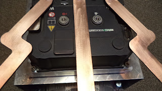
DSC01615 view showing the three bus bars installed.
DSC01613 end view of bus bars and rods. If used, the corners will later be rounded.
DSC01614 top view of Copper bus bars and rods. These "angled" bus bars do not extend excessively from the midline. A box enclosure will be added that is mounted to the top of the motor, the side of the controller box, and the Aluminum support plate. Before installation the bus bars will be tinned, covered with heat shrink tubing as needed, and then slipped into fiberglass insulation.
DSC01765 showing the Aluminum test pieces.
DSC01767 close up of the angle in the Aluminum test pieces. updated 5/16/2023
IMG-6590 of the Copper plate on the plasma cutting table. ( Bart's Precision Machinery and Fab )
DSC01790 The holes in the 0.125" thick Copper washers (picture IMG-6590 above) for the M8-1.25 bolts were drilled to 5/16" and the holes in the Copper washers for M10-1.5 bolts were drilled to 13/32". updated 5/16/2023
Copper washers were plasma cut from scrap 0.125" Copper plate (picture IMG-6590 above). M8 washers can be used to correct for a vertical bus bar height that is too long, and the M10 Copper washers can correct for a bus bar whose vertical height is too short. updated 5/18/2023
DSC01768
DSC01775 showing the area covered by the long bus bars.
DSC01778 showing the use of short bus bars. These bars do not need to cross over the top of the controller and each one uses less Copper. But, these short bars would require that the motor terminals U and W be reprogrammed prior to use.
DSC01779 showing that the existing pre-charge terminal would be covered by the short bus bars. If the pre-charge terminal can be relocated to a vacant area of the controller, then these short bus bars might be used.
DSC01816 showing the terminal block found at the power end of the motor. The bottom block in the picture (when viewed from the end of the motor) is the OEM supplied orientation. During software installation and the motor set up process, the motor can be reprogrammed to reverse terminals W and U. The OEM “U” terminal becomes the new “W” terminal, and the
OEM “W” terminal becomes the new “U” terminal. A later post will discuss this process. To avoid confusion, the four bolts that secure the terminal block can be removed and the terminal block rotated 180 degrees to correspond to the new software assignments.
Use of Copper Bus Bars - Using a Brake Press
DSC01804 An Eastwood brake attachment ( https://www.eastwood.com/eastwood-press-brake-attachment.html ) was combined with a Premium Products 12 Ton Press ( provided by Peter Kola).
DSC01810 end view of the installed and contoured bus bars.
DSC01811 top view of the installed and contoured bus bars.
DSC01763 showing the outlines of the required cuts on the Avery 5165 label paper. These cuts will allow the bus bars to pass though the side of the enclosure.
DSC01813 of the end caps (one was used) that were made from 0.063" Aluminum 5052.
DSC01814 showing the external view. The end caps were 3.375" wide, 2.375" deep, and 7.25" in height. Top seams were welded.
DSC01815 top view of the enclosure end cap..


No comments:
Post a Comment