Saturday, August 17, 2013

Motor Mount 3.5

The initial trial fitting revealed that the 3.75" tall x 4.0" wide flange required more mounting surface at the bottom edge.  New flanges measuring 5.0" tall and 4.0" wide were then fabricated, trial fitted, and hot glued together.


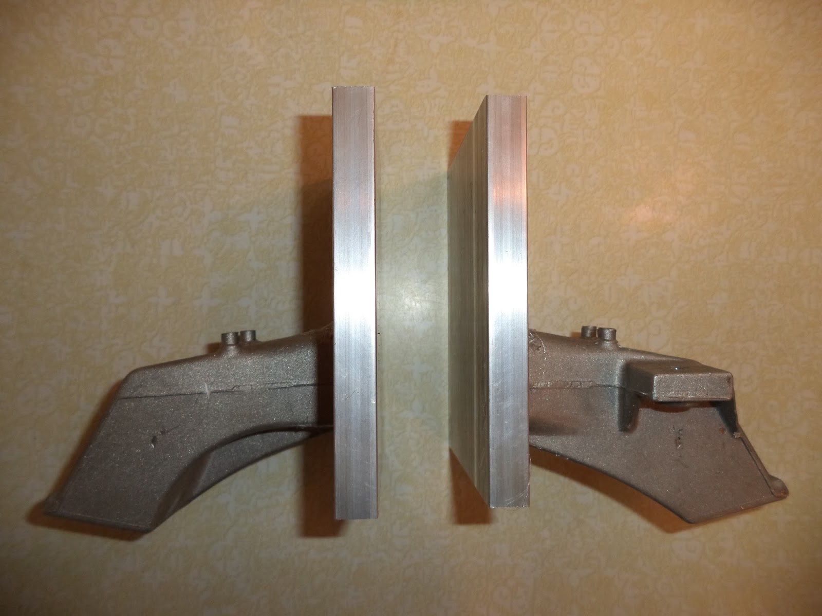
Picture DSC00371 showing the side (viewed from the front of the car) of the new taller flanges fitted to the sectioned BMW OEM parts.


Picture DSC00372 of the passenger side (left) and driver side (right) after being hot glued together.
 
 
It was then desired to weld the sectioned engine mount directly to the flanges.  Although the flanges were known to be alloy 6061, the BMW OEM parts were of unknown composition, and it was unknown whether the two metals would be compatible to welding.  To determine the alloy type of the sectioned engine mount, it was tested with a Glow Discharge Atomic Emission Spectrometer.  The test sample surface was first sanded and then placed within the vacuum chamber of the instrument.  After ablating the surface with a laser, the spectral analysis indicated the approximate (100.19%) composition to be:

Aluminum 81.9%
Silicon 12.40%
Copper 2.99%
Zinc 1.78%
Iron 0.78%
Manganese: 0.20%
Tin 0.14%
 
This data is consistent with an aluminum die casting alloy similar to alloy 380 or 384.  A professional welder was then able to test weld the two parts together using a TIG welding apparatus.  Unfortunately, the hot glue was not strong enough to hold the pieces during the welding process and the precise orientation of the flange to the sectioned piece was lost .  The next attempt will again use the hot glue for proper initial orientation and removal of the two pieces from the car, but, it will then be attempted to spot weld the two pieces with a MIG welder prior to taking the parts back to the professional for final circumferential welding.  


Picture DSC00373 showing the circular impact point left on the sample section of the BMW OEM part after the laser ablated the metal. 


Picture DSC00 showing the first try at welding the BMW OEM part to the flange just prior to drilling the mounting bolt holes.

Sunday, August 11, 2013

Motor Mount 3.0


The fabrication of the flanges for connection of the shortened OEM driver side engine mounts to the top half of the aluminum clam shell began with cutting four 3.75” x 4.0” x 0.5” plates.  Two of them were then drilled to each accept four 5/16”-18 bolts.


Picture DSC00345 showing the four holes and the first countersink drilled into the flange.  The flange is 0.50" thick and the countersink is 0.25" to permit recess of the bolt heads.


Picture DSC00348 showing one of two completed flanges.  The flange (left) was then carefully positioned on  the clam shell (right) and a center punch used to locate the future position of threaded holes in the clam shell.  Note that the left flange was rotated 90 degrees before the picture was taken and when attached to the clam shell it is identical in height (3.75") to the clam shell on the right.


Picture DSC00349 shows the awkward setup that was required to use the Bridgeport to drill holes in the ends of the clam shell.  The mill table was in full down position and there was still barely sufficient clearance to drill the pilot holes in the clam shell.

To prepare the clam shell for 5/16" hex head bolts, the clam shell was first drilled 1" deep with a 17/64”bit.  It was then threaded with a tapered 5/16"-18 tap and finally the threads extended to nearly the bottom using a 5/16"-18 plug tap . 


Picture DSC00356 showing the flange bolted to the clam shell motor mount.  The gap from the face of the BMW OEM piece and the face of the flange is slightly grater than 0.5”.


Picture DSC00361 showing the placement of the second 0.50" flange (center with red X on edge) that will be welded to the remnant of the OEM engine mount (bottom center).


Picture DSC00363 showing the outboard flange hot glued to the BMW OEM engine mount support.


Picture DSC00365 showing a view of the passenger side hot glued pieces as viewed from the front of the car. By hot gluing the two pieces together it was possible to fix the precise orientation top to bottom, front to back, and left to right.


Picture DSC00366 showing the outboard view of the hot glued pieces.  The square flange is connected to the shortened BMW OEM engine mount (foreground).

It is preferred that the BMW OEM engine mounting bracket face be fully welded to the flange on all four sides.  To allow for greater welding surface, a different and larger outboard flange will next be fabricated.  The larger outboard flange and the BMW OEM engine mount will then be welded together at a fabrication shop. It is anticipated that the welder will first tack weld the pieces, then remove the residual hot glue, and finally weld the complete outer circumference of the modified BMW OEM part.