BendPak HD-9 Specifications:
- Lifting Capacity: 9,000 lbs. / 4,082 kg
- Overall Width: 110-1/4" / 2,800mm
- Outside Length: 174" /4,420mm
- Overall Length: 200" /5,080mm
- Height of Columns: 88" /2,235mm
- Runway Min. Height: 4-1/2" /114mm
- Max Rise: 70" / 1,778 mm
- Max Lifting Height: 74-1/2" /1,892mm
- Width Between Posts: 100-1/4" /2,555mm
- Runway width: 19" / 483mm
- Width Between Runways: 37-1/2" - 44-3/8" / 952 - 1,127 mm
- Length of Runways: 164" / 4.166 mm
- Min. Wheelbase @ Rated Capacity: 115" /2,921mm
- Min. Wheelbase @ 75% Capacity: 100" /2,540mm
- Min. Wheelbase @ 50% Capacity: 85" /2,159mm
- Min. Wheelbase @ 25% Capacity: 70" /1,778mm
- Locking Positions: 12
- Lock Spacing: every 4" /102mm
- Lifting Time: 45 sec.
- Motor: 220 VAC / 60 Hz / 1 Ph
- ABTM part number: 7990
The manual (HD-9 version L) as supplied provided most of the necessary information for the building of the lift. To increase confidence, and prior to building the lift, several youtube videos of lift installations were reviewed to see how others had attacked the project.
https://www.youtube.com/watch?v=4SHgSLauUaM&list=PLZU3rdralvGMKEjYOm-VvGhd1AcydgvXV
https://www.youtube.com/watch?v=leYgoqd2i5c&t=212s
Interestingly the videos show very few close up pictures of the details of the construction. The purpose of this posting is to supplement the manual and the youtube videos so that others who may elect to build their first HD-9 lift might be able to save some of the time that I wasted in my first build.
The lift was supplied tightly packed within disposable angle iron end frames as a long rectangle (DSC05593). A forklift was required to unload the 1686 pound shipment.

DSC05593 of the packed lift after removal of the parts boxes that were stacked on top and removal of the cardboard protective coverings.

DSC05625 of the HD-9 lift label serial number 9966-001-012.

DSC05633 Each cross member has 4 black plastic slide blocks mounted to pairs of pins on each side. A mallet was initially used for placement, but some of the blocks did not fully seat, so a "C" clamp was used to squeeze the plastic blocks (DSC05634) closer to the cross beam. Once the bottoms of the plastic blocks were lowered into the column, the "C" clamp was removed, and the crosstube then slid smoothly down the column.

DSC05634 showing the use of "C" clamps for compression of the black plastic slide blocks so that they fit into the column.
When a forklift is not available, some youtube videos show pairs of posts positioned horizontally on the floor ( https://www.youtube.com/watch?v=0EsW7llK5IA ) , and then two workers insert the crosstube at the top of the masts while still at floor level. The crosstube is then pushed toward the base of the column, and finally both columns (now connected with the crosstube) are lifted up to a vertical position. In this blog build a forklift was available, so pairs of the columns were instead positioned on the concrete floor and the crosstubes were lifted and then lowered into the columns. It was also elected to place a pair of empty 55 gallon steel drums under each crosstube next to the columns to maintain a comfortable working height.

DSC05636 showing the use of an empty 55 gallon steel drum to support the pieces during assembly. The Powerside Runway is the length that has the hydraulic ram attached to the underside and it is located next to the hydraulic drive.
The drums created a comfortable working height for access to the underside of the Runway. The second runway is described as the Offside Runway. The HD-9 allows the Offside Runway to be positioned for either narrow or wide cars. The BMW under construction has an outer wheel edge to edge distance of about 65 inches so the Offside Runway was located at its furthest point from the Powerside Runway.

DSC05641 Initially only 2 drums were used to support the lift during construction. While the safety ladders ( "ladders" ) were installed on the Powerside, without thinking "fully", the Offside Runway was then dropped onto the crosstubes before installing the corresponding offside ladders ! Well, the crosspiece ends close to the forklift descended to the bottom of the columns and the whole lift tilted to the side. Ugh. The fork lift was then used to raise the right side back up, 2 more drums added for support, and then the offside safety "ladders" were installed to lock the crosstubes in place.
The Installation and Operation Manual describes "Large Windows" and "Small Windows" in the crosstubes. These openings allow space for partial insertion of the pulleys that are attached to the Powerside Runway. The words Small and Large relate to the height of the openings. The "Large Widows" are in the cross beam that is farthest from the power hydraulic unit and their size allows for two pairs of pulleys (DSC05681). The "Small Windows" are the openings located in the crossbeam adjacent to the power unit and they only have enough height for two single pulleys (DSC05683). It was found to be challenging to install the double pair of pulleys. It was elected to tilt both columns and the crosstube about 20 degrees away from the runway and then "shoehorn" the pulleys into the crostubes. If the manufacturer had made the height of the windows about 1/4" more, it would have been much easier to install the runway.
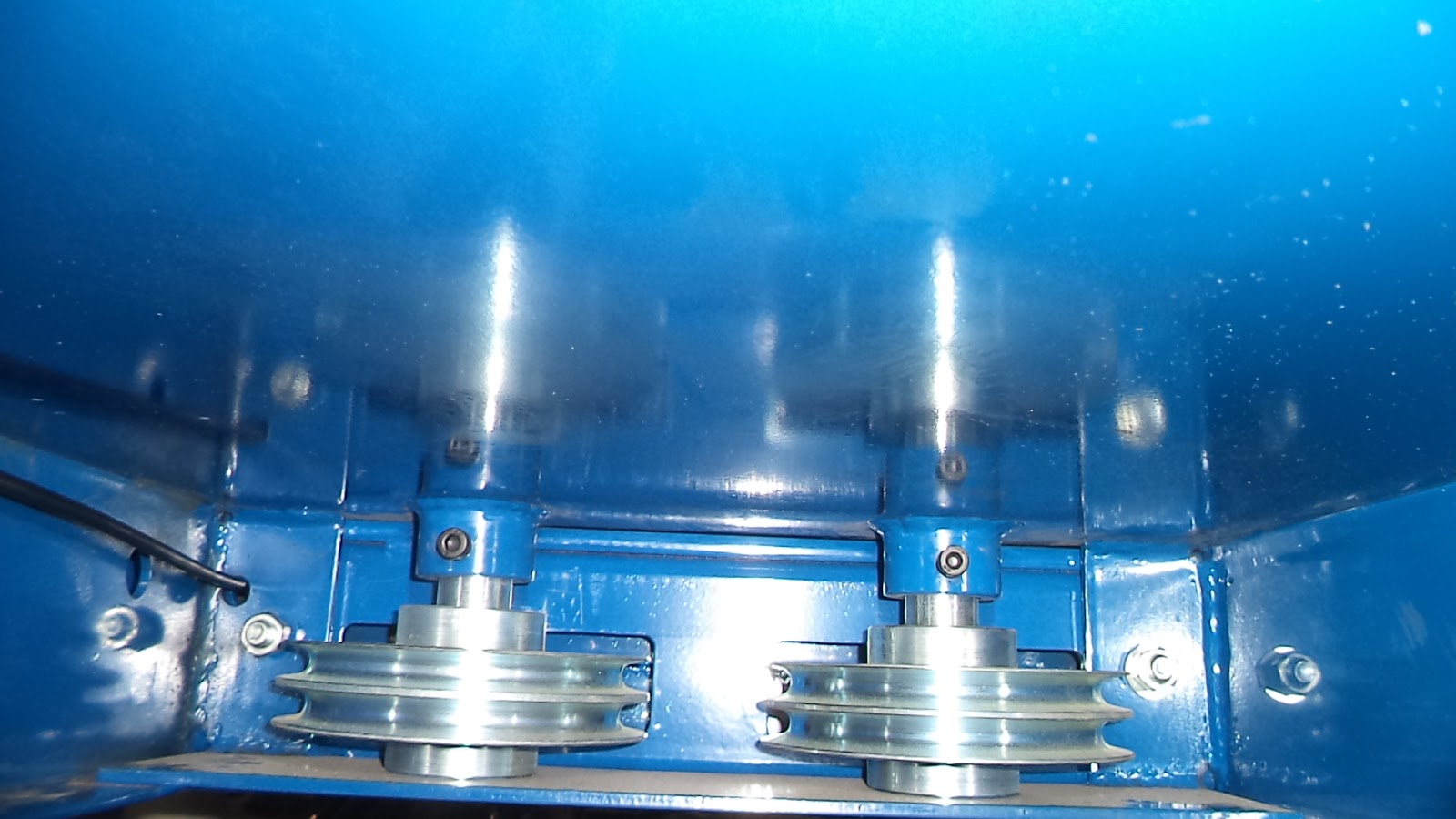
DSC05681 showing the "Large Windows" with the pulleys installed at the far end away from the hydraulic unit. The pulley shafts are retained by the black hex bolts at the top.

DSC05720 after removal of the black hex bolts and the pulley shaft. Picture shows how the shaft is retained by the hex bolt.

DSC058721 showing the incorrect placement of the cable above the corner bolt. When it was hard to feed the cable around the corner bolts it was easier to just remove the corner bolt, push the cable downward, and then reinstall the bolt. This "Large Window" opening is about 1.75".

DSC05722 showing the correct location of the cable below the corner bolt.

DSC05683 showing the left side "Small Window" that is adjacent to the hydraulic unit and is about 1.25" in height.
Extra Parts !!
Then, at the end of the "build", as always it seems, there were some extra parts that somehow were overlooked during construction. After considerable further study, it was decided to send pictures of the parts to the technical service department at BendPak. A teleconference with Abraham quickly determined where the parts belonged.

DSC05642 picture of the four sets of "extra" M10 x 450 mm bolts with nylon insert nuts and Aluminum spacers (cylinders) that have a 1.125" diameter and are 0.625' thick.
The picture above was supplied by Abraham at BendPak Technical Support (800-253-2363, ext. 196) to show the proper placement of the bushings shown in DSC05642 . Note that the bottom edge of the safety ladder (on the left side wall) is clearly above the base plate.

DSC05646 of the "extra" lubricating grease nipples (appears to be Zerk fittings). The fittings were eventually installed using an 8 mm nut driver at the locations shown in pictures DSC05677 and DSC05673 below. A call to the factory confirmed that the pressure fitting (right side) was intended to be installed on the top of the push button switch as shown in picture DSC05671 below. It was elected to substitute this fitting with the fittings shown below in picture DSC05741.

DSC05741 of the air line fittings that were purchased separately and used to supply 30 psi compressed air to the push button switch.

DSC05640 showing the use of a small wrench to grab the spring and hook it around the blue retention peg in the cross beam. This wrench was used to help remove, and then reinstall the springs when needed.


DSC005756 showing the lowering handle (black knob, press to lower) located above the red fill port of the hydraulic reservoir. As the lift is raised there are a series of loud clicks as pins move up the safety ladders. When the lift is raised to its required height, this lowering handle is pressed to allow the lift to settle back down until pins in each column engage the safety ladders. The lift is not considered to be safe for use until the safety pins have locked and the lift no longer descends.

DSC05667 the installation manual (page 25) suggests using 12 quarts 10 WT Hydraulic Fluid or Dexron III ATF. Three gallons of O'Reilly's Premium ATF Transmission Fluid (part D-1, at $18.99 per gallon) was loaded and interestingly, the reservoir dip tube (located under the red cap) still did not show the reservoir as being full to the top.

DSC05757 showing the on/off power switch for the hydraulic pump (upper left in picture on black box). For initial testing the 240 volt plug shown was temporarily installed on the hydraulic unit.

DSC05648 showing correct placement of one of the runway stops. The tabs in the center prevent the yellow stop from falling forward and laying flat on the runway. There are clips on the end of each Aluminum rod (Tire Stop Pin) to prevent it being dislodged.

DSC05691 showing one of the four Aluminum Tire Stop Pins (top right rod) that are used to secure the front tire stops and the approach ramps. The retention clips are described as 12mm SS Rotor Clips on page 27 (figure 16.1) of the manual. The clips fit very snugly, and to facilitate installation, a socket wrench socket was selected whose id allowed the rod to insert, but whose OD matched the diameter of the Rotor Clip. With leather gloves (sharp edges) the socket was then used to force the rotor clips to place. This clip appears to be similar to a DTX-12 Shaft Ring found here https://www.rotorclip.com/cat_pdfs/dtx.pdf .
Hydraulic unit

DSC05638 When working alone, it was convenient to use a car jack to elevate the hydraulic unit while the four mounting bolts were installed. A second helper at this point would have made the process much easier.


DSC05645 of the end of the heavy duty hydraulic line with the 90' elbow. The hydraulic hose then passes through a plastic Flex Hose connected to the powerside runway and it then travels alongside the cylinder before the hydraulic hose's straight end terminates into a 90 degree brass fitting that is attached to the hydraulic cylinder (picture DSC05685).

DSC05685 showing the hydraulic hose (with straight end) connected to the ram end of the cylinder after a 90' fitting (NPT to hydraulic) was installed on the cylinder.

DSC05671 the brass 90' (NPT to air hose) at the picture bottom center (back left side of the drive unit) is connected to the base end of the ram (picture DSC05668) with plastic tubing. This is the hydraulic return line for the ram. The bottom of the push button at the top left in the picture terminates at each of the 4 posts after passing to the tee shown in picture DSC05669. Note that the inlet (top) of the push button switch has the brass fitting previously shown in the picture DSC05646 above.

DSC05668 showing the termination point of the hydraulic return line from the drive unit at the base of the ram cylinder. This hydraulic return line terminated at the left base of the hydraulic unit as shown in picture DSC05671.
Air Actuated Safety Locks
The lift requires a 30 psi air supply to actuate the safety locks located on each column. When air pressure is applied by pressing the auxiliary push button, the air cylinders withdraw the latches on each safety ladder with a prominent click from each ladder. If one then presses the lowering handle (picture DSC05756 above) on the hydraulic drive, the hydraulic fluid within the cylinder then returns to the plastic reservoir located under the hydraulic pump.
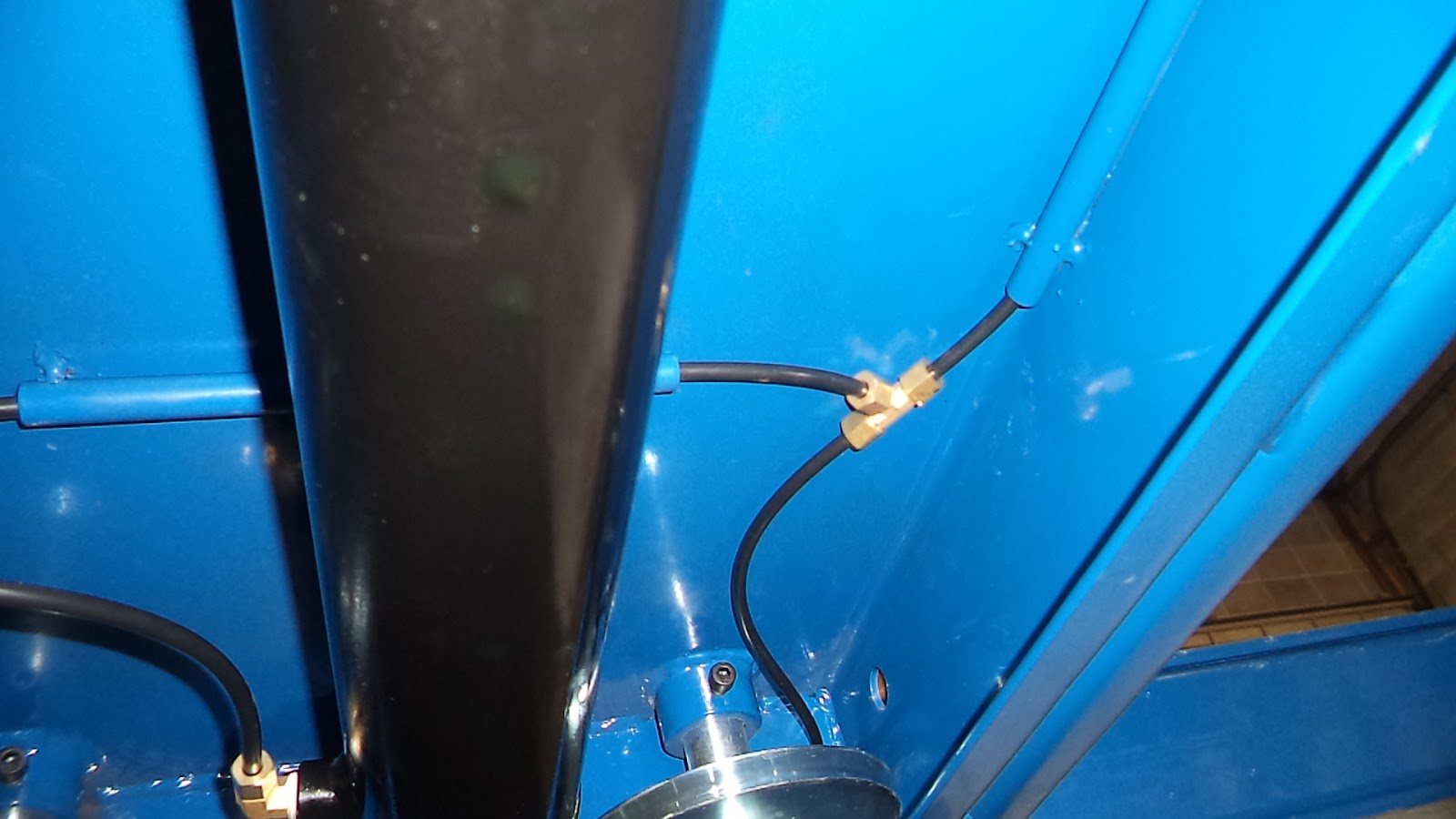
DSC05669 showing the brass tee (right center) where the air line from the bottom of the push button switch terminates. The other black plastic lines from the tee then pass front and back to the cross beams and then branch again to each post. The push button switch along with these air lines direct 30 psi air to a pneumatic piston located in the cross bar by each column (picture DSC05672). When activated, the pneumatic piston disengages the safety locks from the safety ladder with a loud click.

DSC05672 showing the termination of the compressed air line into one of the four pneumatic pistons located adjacent to each cross beam. When pressurized, the action arm disengages the safety pin from the ladder, and if the lowering handle on the hydraulic pump is pushed downward, the hydraulic fluid returns to the reservoir and the lift begins to lower to the ground.

DSC05676 Each pulley shaft has a threaded opening at the bottom. The white pointer indicates where the opening can be found and a close up view is shown in DSC05677.

DSC05677 showing the underside of one of the four pulley shafts located on the powerside runway. An 8 mm nut driver was used for the installation of the Zerk style lubrication fittings.

DSC05673 At the center of the picture can be seen the pulley shaft (with the large E clip ring) into which the Zerk fitting has been installed. Each cross tube has two Zerk fittings.
Floor Mounting
The factory supplies 16 anchors (DSC05710) that are mounted after drilling 3/4" holes approximately 4.5" deep into the concrete floor with a masonry hammer drill. The anchors result in sixteen 3/4" x 2.25" studs protruding from the floor. If it is necessary to relocate the lift to allow movement of other equipment within the facility, the protruding studs would present a problem.

DSC05710 of the factory supplied floor anchors. The anchors result in permanent 2.25' x 3/4" studs protruding from the floor in 16 locations.
Alternatively, it was decided to instead use floor anchors (DSC05711) that mount flush to the floor. The baseplate of the lift is then secured using 3/4" x 3" bolts. By using this alternative design, it is possible to remove the bolts, relocate the lift, and still have full access to the floor area without damage to the forklift tires.

DSC05711 of the alternative floor anchor system that allows for the movement of the lift within the facility without the inconvenience of protruding studs that might interfere with rigging or cause forklift tire damage.
Edited 7/22/2018

DSC06372 Showing one of the 87.125" tall posts prior to placement of floor anchors. The channel opening is the inside face of the post. The post is 6" x 5" tubular steel and the floor mounting plate is 10" (width of the lift) x 12" (length of the lift) x 0.375".

DSC06373 Showing the outside edge and face of the post. The mounting holes are 1" diameter and they are 8" (width of lift) and 10" (length of lift) center to center.
In the following youtube video the HD-9 lift can be seen ( https://www.youtube.com/watch?v=RoUoSKoIb14 ) being moved using the optional BendPak castor kit ( http://www.bendpak.com/car-lifts/accessories/caster-kit.aspx ).
Another video reviews the castor kit. https://www.youtube.com/watch?v=M0QLkzzRDCA
Peter B. and I built the BendPak HD-9 Four Post Lift unit over three Saturdays. With what was learned by this build experience the next installation (also using two people and one forklift) should only require 2 Saturdays to complete.


