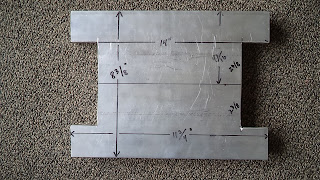
To build the controller support, a sheet of 0.063-0.067" 5052-H32 Aluminum measuring 27" x 10.5" was prepared.
DSC01560 after boring out the fan vents (4.5" diameter) and drilling the 5/32" holes for the mounting bolts, the sheet was bent to shape. The original motor cradles offered by NetGain have a 15 degree flare, so the bottom mounting surfaces of the support plate were bent 15 degrees (relative to the base) to conform. Top bends are 90 degrees. The Top surface is 10.5" x 11.75" with the sides 6.25" x 10.5".
DSC01562 side view showing the pair of 4.5" vents for the box fans and the 5/32" holes for mounting.
DSC01563 test fitting of the platform with the Hyper9.
DSC01647 showing original controller support version 1.0 o n the left and the newer version 2.0 on the right. The left side is compatible with a mounting surface that is 15 degrees from the platform, while the right side is parallel to the mounting surface. Edited 3/23/23
DSC01652 showing the detail of the mounting tabs. The mounting holes on the left have not yet bee drilled. Updated 3/23/23
DSC01645 showing the end on view of the support platform attached to the cradle. Edited 3/23/23
DSC01646 showing Version 2.0 support platform mounted to the cradle. The bottom bolt is initially tightened to compress the cradle against the motor (or in this case the surrogate PVC motor) and after secure, the internal nut is tightened to secure the support platform to the cradle itself. Edited 3/23/23
DSC01690 showing the plasma cutting of a support plate from a 0.067" x 48" x 48" 5052-H32 Aluminum sheet. ($45 from Alro Metals). A Langmuir Systems - Crossfire Pro (at Bart's Precision Machinery and Fab) was used with a total cutting time of 93 seconds per piece. Updated 4/9/23
DSC01646 showing Version 2.0 after being cut, but prior to drilling the fan mounting holes, and bending to shape.
Heat Sinks Mounted to the Controller Support
DSC01569 showing the maximum length cooling heat sink (11.75" L x 7.25" W x 1.25" D with 1.0" fins) with both fans mounted externally. The fans do not clear the fins.
DSC01575 rear face of 11.75" x 8.375" heat sink after removing material to provide for fan clearance.
DSC01574 front face of 11.75" x 8.375" heat sink after removing material to provide for fan clearance.
DSC01619 view from the bottom of the "modified maximum length" heat sink in place. A wider heat could be used.
A more elegant heatsink was later machined from a second piece in which only the fins were removed in the area of the box fans.
Edited 3/24/2023
DSC01639 Closeup of the side of the heatsink shown in DSC01571 above. The heatsinks are generally not flat and there is a slight curvature. To obtain a precision contact surface between the heatsink and the controller base, the heatsinks must be machined perfectly flat prior to installation.
.
Edited 3/25/2023
DSC01654 Closeup view of heatsink shown in DSC01571. The 1.25" x 1.25" x 0.125" Aluminum angle was cut to 9" length and drilled for attachment to the heatsink and the mounting surface.
DSC01653 Back side surface of heatsink shown in DSC01571 above. Heatsink base is is 9" x 7.25" and the overall height is about 1.305".


No comments:
Post a Comment