Sunday, May 20, 2018

Tesla Battery Interface Wiring Diagrams Preliminary # 1

THIS POSTING IS PRELIMINARY AND WILL BE UPDATED AS THE BUILD AND TESTING CONTINUES.  ALL READER COMMENTS ARE GREATLY APPRECIATED.

The purpose of the EVBimmer battery interface boards is to protect the Orion Management System and the sensor wires of the Tesla modules in the event of a short circuit or improper wiring.  An open circuit will be sensed by the Orion but a shorted lead will result in one or more blown fuses.  Orion indicates that the maximum voltage between any two terminals should not exceed 5 volts.


DSC06336 image of the preliminary wiring diagram that connects the Orion to Tesla module number 1.
 

UPDATED 2/19/2019 and 3/6/2019


Preliminary testing has resulted in a design change.  Previously used was the zener diode 1N4732A which is rated at 4.7 volts and it was found that on power up, transients can sometimes cause the diode to fail.  The diode value has now been changed to a zener 1N4733A which is rated at 5.1 volts.  The Orion uses an internal 5.6 volt zener, and our intention is to operate just below the Orion specification in an effort to further protect the Orion.  We are also experimenting with the use of fast blow fuses to see if they can further protect both the Orion and the diodes. 

Cell 6A of the EVBimmer J1 Terminal Block on Tesla Battery Module #1 is connected to Cell 0 of the EVBimmer J1 Terminal Block connected to Tesla Battery Module # 2.


DSC06337 image of the preliminary wiring diagram showing how each Tesla module is daisy chained. 

NOTE:  A testing board is now being made that will mimic a pair of Tesla battery modules.  Using a series of resistors and the 12 volt supply ( required to operate the Orion ), it is possible to provide a chain of current limited low voltages that the Orion can sense and be monitored by the Orion software.  With jumpers it will also be possible to short out individual "cells" of the testing board and the Orion software will be able to respond to each change observed.

Orion BMS-48 Cell Kit Controller For Charging Six Tesla 5.3 kWh Battery Modules

An Orion BMS-48 Cell Kit controller was purchased ($1205) from EVolve Electric.  This kit included:

Main Controller
     Orion 48 (REV - E2)
     Serial # L4574D00 ;
36 Cell Tap Harness;
12 Cell Tap harness;
I/O Harness;
400 Amp Current sensor with (4) Pre-Wired Thermistors;
CAN adapter;
and a Utility Disk CD which contains the Orion BMS Utility
(also found here: http://www.orionbms.com/manuals/utility/ );
Software Manual (also found here:  https://www.orionbms.com/features/pc-software/  );
and Wiring Manual (also found here: http://www.orionbms.com/manuals/pdf/wiring.pdf ).

Since the Tesla batteries each have 2 thermistors and the six Tesla modules require a total of 12 sensors, an Orion Thermistor Expansion module was purchased ($207).  This module interfaces with an additional 80 thermistors.

To facilitate wiring the Thermistors to the Orion BMS an 6' Orion Thermistor Wiring Harness was purchased ($52) which has 20 pre-populated thermistor taps.


DSC05617 oblique view of Orion BMS enclosure.


DSC05618 bottom view of BMS enclosure


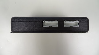
DSC05614 side view of Orion BMS enclosure (2 connectors + Ethernet?).  The Thermistor / Current Sensor socket on the far left connects to the white 16 pin plug labeled 371 and shown on the left side of picture DSC06316.  The larger white socket on the right is labeled the Main I / O Connector and it mates to cable CWHMIO2-W1546D19 shown in picture DSC06322 below.


DSC05613 side view of Orion BMS enclosure.  The far left socket is used for Cell Groups 1-3 and the middle socket is used for Cell Groups 4-6.  The far right hand socket is not used.


DSC05600 of the Orion BMS Thermistor Expansion Module that permits xxx different Thermistors to be monitored.


DSC05601 of the Orion Thermistor Expansion module (three connector)

Cable labeled WHTHEXPO2-W156640 (picture DSC06315 shown below) connects to the far right socket.


DSC05602 of the Orion Thermistor Expansion module (two connector)


DSC05609 top view of 400 amp current sensor.  As shown above, the power cable opening is 21.57 mm ID left to right, and 22.62 mm ID top to bottom.


DSC05608 of the current sensor showing the internal pins labeled D, C, B , and A.  This current sensor mates to the purple cable socket (part number CWHCURTH-W1559453) shown  below in picture  DSC06316.

The current sensor has the following markings:

LEM
716183093257
>PA66-GF25<


Wiring harnesses that were included in the Orion BMS-48 Controller.


DSC05619 of the multiple wiring harnesses provided. 

The part numbers as printed on the exterior of the plastic bags were sometimes different than the part numbers located internally so both numbers are listed.

(starting at 12:00 - top center ):

CWH126-W1472408, with internal part number CWH126 KSM1915


DSC06308

 
DSC06307

This cable has 12 orange wires labelled 1 to 12 and 1 black wire labeled 1.  Plastic plug is labelled 369.

WHTHEXPO2-W156640, with internal part number of  CWHTHEXP02 KSM5216.


DSC06315


DSC06314

7 wires, with bottom row (as shown):
blue, black, purple, yellow and black.
top row with red, followed by 3 empty plug locations, and finally a red wire.  The first black wire is paired with the first red wire in the lower row.  The plastic plug is labelled 420.  This cable connects to the Orion BMS Thermistor Expansion Module in the far right socket shown in picture DSC05601.

CWHTP-W1574C00, this cable had an internal part number of  CWHTP KSM0817


DSC06304


DSC06305

A pair of wires, orange and brown.  Black cable covering.  8 wire plug using only 2 wires, orange and brown.  The plastic plug is labeled 384.

CWHMIO2-W1546D19 (bottom right of picture DSC05619) had an internal part number of CWHMI02 KSM4716.  The cable package also included 3 x 120 ohm resistors (DSC06334).


DSC06322


DSC06321

Appeared to be 18 wires, but the 2 black wires ( 1 short and 1 long) were actually 3 wires each, both sets covered in black sleeves.  The plastic plug is also labeled 371 and it connects to the right side socket shown in picture DSC05614 above.


DSC06334 of what appears to be 120 ohm resistors.


CWH366-W155550F with an internal part number of CWH366 KSM5116.


DSC06313


DSC06312

A black wire followed by 12 orange wires (labeled 1 to 12), then a black wire followed 12 red wires (labeled 13 to 24) , then a black wire followed by 12 yellow wires (labeled 25 to 36), and finally a black wire.  The black wires are labeled 1, 13, and 25.  The plastic plug is labeled 420.

CWHCURTH-W1559453,  this part had an internal part number of  CWHCURTH-D  KSM5016.


DSC06316

This cable has a white plug, a purple plug, and 4 pairs of black wires.  On the side of the purple plug (which has an external black housing and 4 wires connected to it) is indicated:  DELPHI  11  PBT-GF20.  This purple plug attaches to the current sensor shown in picture DSC05608 and 5609 above.  When the purple plug is viewed as in picture DSC06316 above, the far right is pin A and the far left is pin D.  


The white plug has 12 wires (4 go to the purple plug) and the white plug is labeled 371.

THERM2002-W1573D0B, which appears to have 20 thermocouples with 2 wires each.

CWHTHEX202-W1531B?  (center of picture), this part had an internal part number of HTHEX202  KSM4116. 


DSC06320


DSC06319


DSC06318

top row: black followed by 5 white, then black followed by 5 white.
lower row, identical to upper row.  The plug is labeled 371


DSC05620 of the CANDAPTER CAN bus interface with software


Monday, February 5, 2018

Tesla 5.3 kWh Battery Module Monitoring Board - Part 2


Previously (this blog 12/8/2016) the Tesla Battery Module Monitoring Boards were described and later an interface board (this blog 5/15/2017) that allows Tesla batteries to be connected to an Orion battery management system.

Jaroslav Alexa in the Slovak Republic ( jaroslav.alexa@gmail.com  ) made contact and he is working on a 1993 Opel Calibra .  He plans to maintain the 2.0i gas engine in the front but add an AC75 with Curtis controller that is powered with 4 Tesla batteries in the rear.  To interface the batteries he ordered 4 of the EVBimmer battery interface boards.


Picture JA214814 showing that the top of Jaroslav' board which appears to be equivalent to the boards previously examined (this blog 12/8/2016).

Jaroslav's Tesla battery board has the following markings:

PCBA, BMB, WIRE-CLP  (perhaps Printed Circuit Board Assembly, Battery Management Board)
1014183-00-0  Rev 0
2113C50004242  (perhaps 21st week of 2013)

Our Tesla battery boards have the following markings:

PCBA (1020796)
1021749-00-B Rev 03
0313KD0001147  (perhaps 3rd week of 2013)

Although the front face of the Tesla battery board appears to be identical to the boards that we have worked with, and it appears that both boards were manufactured at about the same time, the circuit board back side is different in that the sensor wires are directly soldered to the PC board without using any sockets.  (Pictures JA205319 and JA212739).


Picture JA205319 showing the back side of Jaroslav's board while it was being removed from the battery module.


Picture JA212739 showing what appears to be the same J1 inter battery connector (lower left with 2 green dots) but the other jumpers are all soldered directly to the PC board.


Picture JA215550 side view of  J4 (right) J3 (right top) and J5 (left center).   All connections were soldered to place.
 
If the white plastic connectors on the EVBimmer interface board are removed it is then  possible to directly solder the sensor wires to the board.


Picture JA212242 showing the connections after Jaroslav finished soldering the wires to the back side of the EVBimmer board.  He was able to make the new connections without removing the sockets on the front side of the board.  The wire leads from the Tesla module are not very long and a white wire was used to extend the length of the Tesla Orange wire.

Alternatively the sensor wires can be attached to the corresponding plastic connectors that would then permit direct connection to the EVBimmer board.

The surface mount connectors (male) used on the EVBimmer interface board are parts numbered S15B-PASK-2 (LF)(SN) and S04B-PASK-2 (LF)(SN).  Both can be ordered directly from JST in Japan.   As of this writing the S04B can also be obtained from DigiKey.com  .

The corresponding mating connectors (female) that would then attach to the EVBimmer board's connector include the housings (parts numbered PAP-15V-S and PAP-04V-S) and the pins (part number SPHD-002T-P0.5 ).  All of these parts are available from DigiKey.com  .  To attach the pins to the sensor wires requires a micro crimper and an Engineer PA-09 Micro Connector Crimper can be used.  The crimper is available for $38 from Amazon.com and can be found here:

https://www.amazon.com/Engineer-PA-09-Micro-Connector-Crimpers/dp/B002AVVO7K/ref=sr_1_1?ie=UTF8&qid=1517513466&sr=8-1&keywords=pa-09