A bandsaw, 12 ton press, and an Eastwood brake, were used extensively to produce the bus bars required to interconnect the "Power Input to the Master Shut off to the Gigavac Contactor to the Ferraz-Shawmut 500 amp Main Fuse to the Controller B+ Terminal". All bus bars were of 0.125" x 1.0" wide Copper plate. The contactor and main fuse were mounted to an Aluminum platform that will be described in the next post. The height of the platform placed the contactor, fuse, and controller terminals all in the same plane.
DSC01869 of the power input B+ (top right) bar connecting to the top half of the main shutoff switch (top left). This bus bar was previously described in the May 18, 2023 post.
DSC01867 Bus bar to connect the master shut off switch B+ to the contactor prior to placement. The piece was made from a piece of 0.125" x 3" long x 2" wide Copper plate that was bent into a 90 degree angle with the press brake.
DSC01868 Bus bar connecting the master shut off switch B+ to the contactor (middle back of picture) after installation. Removal of the Copper bar adjacent to the nuts (lower right) allowed for the use of a 17 mm socket wrench for tightening.
DSC01860 Bus bar for connecting the contactor to the main fuse prior to placement.
DSC01861 Bus bar connecting the contactor to the main fuse after installation.
DSC01862 Side view of bus bar connecting the contactor to the main fuse after installation. By taking advantage of the same height for the surfaces, no bends were required in the bar.
DSC01873 Side view of the bus bar Ver. 1 connecting the main fuse output to the controller B+ terminal prior to placement.
DSC01875 Oblique view of the bus bar Ver. 1 connecting the fuse output to the controller B+ terminal prior to placement.
DSC01871 Bus bar Ver. 1 connecting the fuse output to the controller B+ terminal after installation. The overall height above the mounting points is 1.25". Note that there is easy access to the B+ pre-charge terminal underneath this bar.
edited 5/31/2023
DSC01888 Bus bar Ver. 2 connecting the fuse output to the controller B+ terminal after installation. Making the vertical height and the tab length at 1.25: fit the press brake well, but a 1.0" height and 1" tab length was difficult. The use of a vise and mallet was required to finish the job.
DSC01889 Bus bar Ver. 2 connecting the fuse output to the controller B+ terminal after installation. No loss of access to the B+ pre-charge in this smaller lighter version. The overall height is now 1.0".
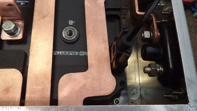
DSC01876 Showing the close proximity of the controller's K3 RS-232 serial port to the Power B- terminal on the cabinet (bottom right side).
Edited 5/30/2023
DSC01878 Showing the manila folder cardboard test model that was used during the design process (the wooden rod for additional rigidity).
DSC01884 Showing the preliminary Aluminum test model fashioned after the cardboard test piece. Note that there is significant clearance around the RS-232 serial port
DSC01883 Detail of the connection at the power B- input terminal on the side of the cabinet.
DSC01887 Showing the vertical height of the Aluminum test bus bar above the U1,V1, and W1 controller terminals. The final bus bar will next be fabricated in Copper.


