Sunday, August 6, 2023

Determining the Vertical Orientation of Getrag Transmission Relative to the Adapter Plate

 When making the previous adapter plate for use with a Warp11 series NetGain motor, the rotational orientation of the adapter relative to the motor was not critical as the power cables exited on the side of the motor.  By contrast, with the Hyper9, it is desired to locate the three terminals at the top of the motor, and all in a plane parallel to the floor.  If so located, then it will be possible to attach a controller or controller housing box directly on top of the Hyper9.  


DSC01947 Picture of a the Getrag 5 speed transmission installed in the E36.  Note that the seam in the transmission casting seam is exactly at the bottom and center when installed.  The center part of the cross piece is parallel to the floor, and thus perpendicular to the transmission seam.  Note that the mounting points on the right are higher then on the left.

To mimic the installation of the transmission, a spare gear box suspension cross piece (BMW OEM  23701136498, $58.93 on eBay) along with a pair of rubber bearings (BMW OEM 22316799331, $21.52 on eBay), were then attached to the transmission tail.  Two pairs of fully threaded bolts allow the transmission to sit squarely on the floor.


DSC01970 Top view of the rear transmission  suspension cross piece.  Top of picture is toward the front of the car. 


DSC01971 The fully threaded M12-1.75 ( L=  40 mm left and 90 mm right) bolts allow the transmission suspension cross piece to be leveled when resting on the floor.


DSC01978 Showing the adapter plate attached to the transmission on the left and the tail of the transmission mounted on the suspension cross piece on the right.  


DSC01980 Close up of the mounting.  The 4 bolts of the suspension cross piece permit leveling of the transmission from each direction.  


DSC01988 Showing the location on the current adapter plate where the top of the Hyper9 will be located.  When the Hyper9 is attached the center terminal will be in this plane. 

The Hyper9 has four mounting holes that relative to center and vertical are located at 45, 135, 225, and 315 degrees.

DSC01967 of the serial number for the transmission for the transmission being used.

This transmission 4USCC7328SLA01518  (2 121 643) has a slightly smaller outer contour when compared to the existing adapter plate.  This was also the case with the other Getrag transmission that was used. 


DSC01968 The bolt pattern is identical but the transmission contour is smaller then the adapter plate..  


DSC01969 Showing the slightly smaller outer contour for the entire periphery.  Bolts used for the pair of dowel pins is M12-1.75 x 90mm.

Friday, June 30, 2023

Adapter Plate Revisit 2023 - Part 1


Hexagon Absolute Arm 8525 7-Axis 2.5 Meter with AS1 Scanner

After talking with Dana Green at Exact Metrology (office 262-533-0797), traveled up to Brookfield, Wisconsin with the Getrag 5 speed transmission and watched as it was scanned.  The laboratory time was a little more then an hour, and the DXF file was returned to me the following day after the computer work had been completed.  Total charges for a simple 2D scan was $500.  

Exact Metrology

20515 Industry Ave

Brookfield, WI 53045


New location as of 9/1/2023 is:


3811 N Holton St

Milwaukee, WI 53212


DSC01918  Picture of  the Hexagon Absolute  Arm 8525 7-axis 2.5 meter with AS1 scanner.  The arm was secured to a large 7800 pound steel table.  These tools with software have a list price new of  $90-95,000 for a turnkey system.  This picture shows the beginning of the scan of the Getrag 5 speed transmission housing face.  The number (946273) in the top left corner of  the monitor is the number of data points collected so far.  


DSC01922 of the hand held AS1 Scanner.


DSC01919  The blue line is the actual data point collection area, and the red line outlines the window within which the blue line must reside for data acquisition.  The scan is a series of smaller "paint strokes" that the computer merges to create the 2D or 3D data set.  The final scan accuracy is expected to be +/- 1.5/1000" ( which is +/- 0.0381 mm).


DSC01921 Showing the green area of the fresh data points just collected, the grey-black area is of those points already logged, and the blue area shows the back side surface points for the collected data. 

The DXF file will next be given to the CNC shop and the adapter thickness and Hyper9 motor orientation added to create a 3D file.  Two adapter plates will be machined from a pair of 7075 Aluminum billets that are 2" x 13.5" x 18.75".  (ALRO Outlet in Elk Grove Village, Illinois at $185 each, or $3.49/ pound).

Note:  To see the previous posts regarding the efforts to make previous versions of the Adapter Plates, enter "Adapter Plate" into the "Search This Blog" window at the right of the page that includes the most recent blog entry.  

Monday, May 29, 2023

Internal Shelf Within the Hyper9 Control Cabinet

 A piece of 5052 Aluminum 0.061" x 26" x 27" was purchased at ALRO Metals Outlet ($14.00),  A 10.5" x 6.25" section was cut (DSC01847), and then formed into a platform with a top area of 10.5" x 3.25" and a height of about 1.625" (DSC01853 below).  The Gigavac contactor and the Shawmut fuse will be secured to the platform, and both will be significantly above the chiller plumbing.

DSC01847 showing the dimensions of the 5052 Aluminum plate prior to cutting with a bandsaw.

DSC01853 showing the end view of the formed platform.  The height to the top of the platform is 1.625".

DSC01855 showing the pair of slots that were cut in the platform to allow for the chiller coolant pipes.  The platform is upside down in this picture.

DSC01859 after placement of the Aluminum platform.

This platform fit easily between the cabinet wall and the controller (DSC01859).  The height of platform was the maximum possible that would allow a simple Copper 90 degree angle to be fabricated and used to connect the contactor and the bottom terminal of the main shutoff switch. 

Copper Bus Bars Internal Connections

A bandsaw, 12 ton press, and an Eastwood brake, were used extensively to produce the bus bars required to interconnect the "Power Input to the Master Shut off to the Gigavac Contactor to the Ferraz-Shawmut 500 amp Main Fuse to the Controller B+ Terminal".  All bus bars were of 0.125" x 1.0" wide Copper plate.  The contactor and main fuse were mounted to an Aluminum platform that will be described in the next post.  The height of the platform placed the contactor, fuse, and controller terminals all in the same plane.

DSC01869 of the power input B+ (top right) bar connecting to the top half of the main shutoff switch (top left).  This bus bar was previously described in the May 18, 2023 post.  


DSC01867 Bus bar to connect the master shut off switch B+ to the contactor prior to placement.  The piece was made from a piece of 0.125" x 3" long x 2" wide Copper plate that was bent into a 90 degree angle with the press brake.    

DSC01868  Bus bar connecting the master shut off switch B+ to the contactor (middle back of picture) after installation.  Removal of the Copper bar adjacent to the nuts (lower right) allowed for the use of a 17 mm socket wrench for tightening. 

DSC01860  Bus bar for connecting the contactor to the main fuse prior to placement.

DSC01861  Bus bar connecting the contactor to the main fuse after installation.

DSC01862  Side view of bus bar connecting the contactor to the main fuse after installation.  By taking advantage of the same height for the surfaces, no bends were required in the bar.

DSC01873  Side view of the bus bar Ver. 1 connecting the main fuse output to the controller B+ terminal prior to placement.

DSC01875 Oblique view of the bus bar Ver. 1 connecting the fuse output to the controller B+ terminal prior to placement.

DSC01871  Bus bar Ver. 1 connecting the fuse output to the controller B+ terminal after installation.  The overall height above the mounting points is 1.25".  Note that there is easy access to the B+ pre-charge terminal underneath this bar.     

edited 5/31/2023

DSC01888 Bus bar Ver. 2 connecting the fuse output to the controller B+ terminal after installation.  Making the vertical height and the tab length at 1.25: fit the press brake well, but a 1.0" height and 1" tab length was difficult.  The use of a vise and mallet was required to finish the job.


DSC01889 Bus bar Ver. 2 connecting the fuse output to the controller B+ terminal after installation.  No loss of access to the B+ pre-charge in this smaller lighter version.  The overall height is now 1.0".


DSC01876 Showing the close proximity of the controller's K3  RS-232 serial port to the Power B- terminal on the cabinet (bottom right side).   

Edited 5/30/2023

DSC01878 Showing the manila folder cardboard test model that was used during the design process  (the wooden rod for additional rigidity).


DSC01884 Showing the preliminary Aluminum test model fashioned after the cardboard test piece.  Note that there is significant clearance around the RS-232 serial port 


DSC01883 Detail of the connection at the power B- input terminal on the side of the cabinet.


DSC01887 Showing the vertical height of the Aluminum test bus bar above the U1,V1, and W1 controller terminals.  The final bus bar will next be fabricated in Copper.


Saturday, May 20, 2023

Chiller Plate Plumbing Incorporated into the Controller Enclosure

Using Aluminum pipe, the hose barbs connections to the chill plate (which may leak over time)  were located external to the enclosure.   A coolant leak within the controller box would likely go unnoticed until damage has already been done.  Teflon tape will be used on all threads and the enclosure penetration will employ grommets to reduce dirt and water entry.    

All fittings are 1/8" NPT Aluminum and were sourced from McMaster-Carr:

2 x 90 degree elbow, part 44705K266, at $5.87 each;

1/8" pipe x 1.5"L nipple, part  44665K161, at $1.97;

1/8" pipe x 2.5"L nipple, part 44665H121 at $2.59:

1/8" pipe x 6" nipple, part 44665k119, at $4.75;

1/8" pipe x 8"L pipe nipple, part 44665K411, at $6.03:

qty 2 x 1/8" pipe to 1/4" hose barb, part 5357K51, at $7.44 each.

2 x Buna-N Rubber grommets, A=11/16", B=1/16", C=7/16", D=15/16", E=5/16".  Part  9307K25 at 50 for $10.91.


.


 DSC01761 of the above Aluminum fittings finger tightened to the controller (this shows an exit to the high voltage side).

DSC01760 after placement of the controller enclosure as a trial fitting showing that after tightening there will be room for the tubing.  Two holes with grommets will be prepared through the left wall of the enclosure for exit of the tubing (this shows an exit to the high voltage side).


DSC01830  after final installation with tubing exit to the low voltage side.


DSC01829 close up showing the exit of the cooling lines on the low voltage side.  The USB port for motor programming is at the top. Did not have an 11/16" drill and instead used a step drill and measured the opening with calipers until sized correctly. 


DSC01831 showing an Aluminum plate located internally for mounting of additional components.


DSC01832 showing possible placement of components.  Power feed at upper left, master shutoff switch (red handle) lower left, controller top center, 500 amp fuse lower row (second from left), contactor (third from left), and optional amperage current sensor bottom right.

Thursday, May 18, 2023

Rincon Power High Voltage Battery Disconnect HVBD4AXR

HVBD4AXR - 400 A Continuous High Voltage Battery Disconnect

A Rincon high voltage battery disconnect was selected for mounting on the controller enclosure as a maintenance switch.  This switch is available in 300A, 400A, and 600A versions.  The 400 amp (continuous) version was selected and it can handle up to 2000 amps for one minute. (EV West sells for  $159).

The disconnect switch data sheet can be found here:

https://uploads-ssl.webflow.com/605a2a14a7fc9726a217b0b2/6261cad9b014d13f844e4d93_HVBD%20SERIES%20DATASHEET_REV_D.pdf 


DSC01741"external view" of the Rincon power switch in the "on" position.  The M8 mounting holes are 100mm center to center. The bolts are torqued to 110-120 IN-LB.  The handle is equipped with a lockout-tag out feature that accommodates a lock whose shank is less than 8.2 mm (0.32").  In this picture the switch is in the ON position.

DSC01744 of the "internal view" of the Rincon power switch. 


DSC01745 side view showing the M10 (316 SS) electrical studs are torqued to 90-100 IN-LBS.  The diameter of the switch body is 68.65 mm  (2.70 ").


DSC01762 after attaching Avery 5165 shipping label stock to the side of the controller enclosure and outlining the required cuts needed to mount both the Rincon HVBD4AXR switch (right) and the Rebling 7009-3 power receptacle (left).

The Avery adhesive on the back of the label is very strong.  If was found that using a propane torch to heat the reverse side of the Aluminum resulted in softening of the adhesive.  It was possible to use a plastic putty knife to scrape off nearly all of the label.  Acetone on a cloth was then used to remove any residual film.


DSC01808 of the Rincon disconnect switch mounted on the side of  the controller enclosure. The switch is in the off position with a lock in place.


Connecting the Master Switch to the Power Receptacle

 updated 5/23/2023

A bus bar was prepared using a 0.125" x 1" x 5.625" copper plate.  


DSC01836 showing the length dimensions.  


DSC01837 showing bend height. 

DSC01833 after installation of  the bus bar.  The height of the bend was slightly smaller then needed and a 0.125" copper washer was used on the power receptacle (upper right) to compensate.


DSC01834 side view of installed bus bar that connects the master shut off switch (Rincon) and the Rebling 7009-3 power receptacle.  In the foreground is the controller U1 bus bar.


Main Battery Pack Connector and Control Box

Purchased from EV Motor Verks Store (573-388-4580, sales@evtv.me) a Rebling 7009-3 Battery Receptacle ($88) and a Rebling 7016 Battery Disconnect Plug Cable Mount ($290).  The 7009 is equivalent to the Rebling 7002 connector and the connector set is rated at up to 750 volts DC, 750 amps continuous, and up to 1500 amps peak.  These connectors are rated for aircraft use and they are positive locking and very robustly manufactured.

Data sheets can be found here:

https://rebling.com/pdf/Rebling___Datasheet-Product___7016%20Avionics%20Cable-Mounted%20Plug%20ver%2020220602.pdf

https://rebling.com/products/two-wire-avionics-plug  

DSC01728 picture of assembled female Rebling Plastics 7016 (right side) and male Rebling Plastics 7009 (left side, equivalent to Rebling 7002).   


DSC01705 view of openings that allow for 2/0 electrical cables.


DSC01726 showing the 7009-3 (Top) and the locking plunger (center) that is rotated into the receptacle using the half-turn handle.  


DSC01703 left side is Rebling 7009-3 (male) and on the right side is the Rebling 7016 (female).


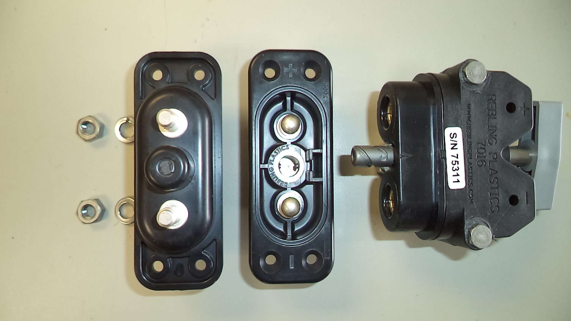
DSC01731 showing the Rebling 7009-3 (terminal studs, 5/16-18, far left as would be viewed from within the control box), middle (male, as would be  seen from outside the control box) and the Rebling 7016 (female) far right top view. 


DSC01723 exploded view of the Rebling 7016 connector.  5/16-18 studs (center) are shown securing a pair of  2/0 terminal lugs.  The far left and far right plastic housings are bolted together with a pair of 10/32 x 1.625" bolts.


DSC01725 showing 7016 after installation of (+) and (-) 2/0 power cables.


DSC01801 showing the installed Rebling connector (left side) on the side of a controller enclosure.  The 7009-3 fits within a 1.50" x 2.90" opening in the controller box.   

The rounded part of the 7009-3 are 1.375" diameter with a center to center distance of 1.54".

A cardboard template of the 7009 was prepared and used to mark the Aluminum of the box before cutting.

The four mounting bolts are 10-32 x 0.5" and Stainless Steel was selected.