
Picture DSC05031 showing the now thinner spacer located between the end plate of the Warp 11 and the transmission adapter plate. Note that the hub adapter shaft is now nearly fully inserted into the adapters.

Picture DSC05030 showing 35.9 amps current draw when bench top tested with a 12 V shop battery. The motor just purrs and you can hardly tell it is even running. Essentially no vibration!

Picture DSC05032 demonstrating the insertion of the plastic clutch plate centering tool into the bronze bearing for the proper positioning of the clutch plate.

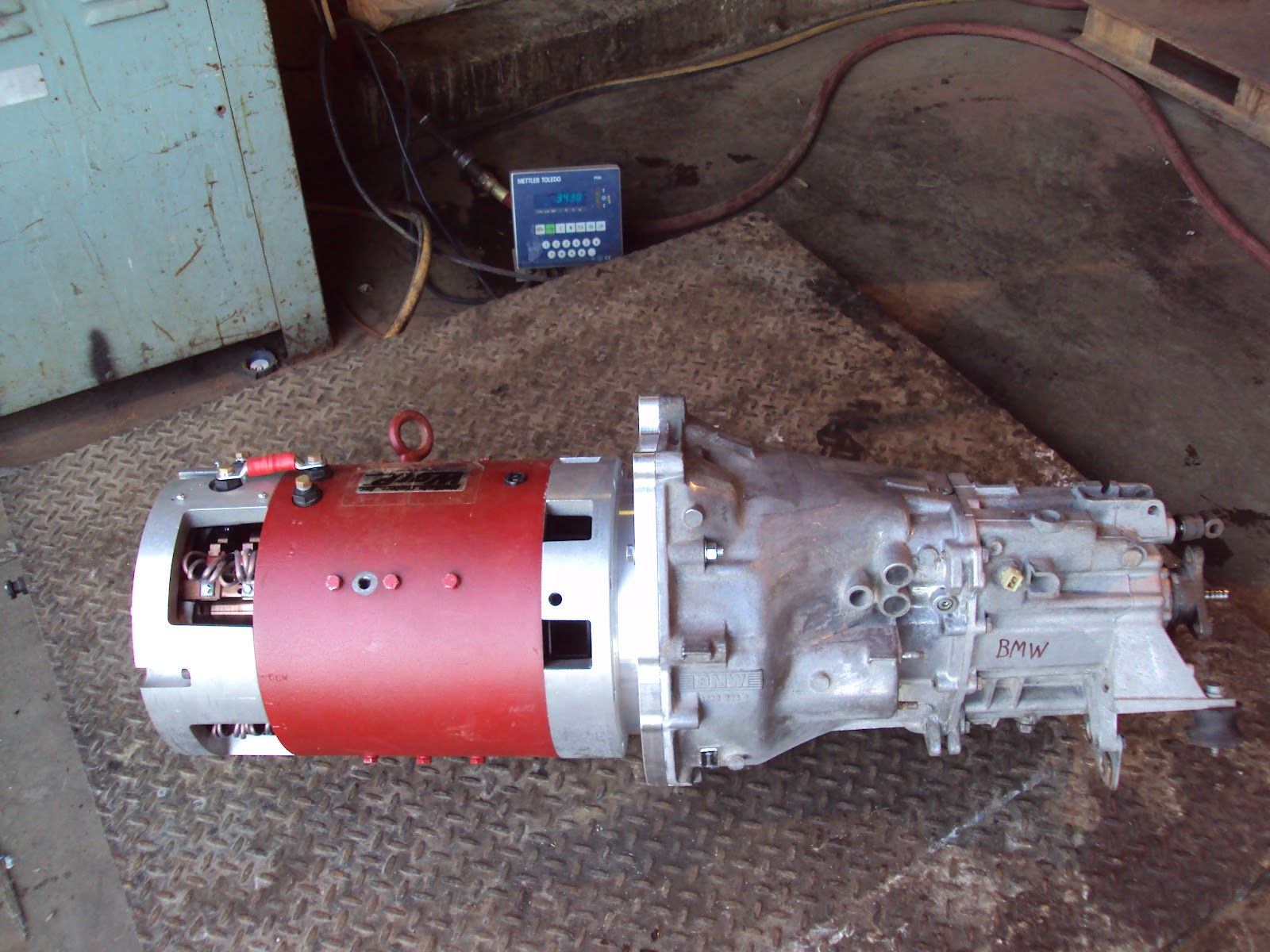
Picture DSC05037 showing the fully assembled drive train weighing in at 343 pounds. The drive train includes the Warp 11, hub and transmission face plate adapters, flywheel, clutch plate, pressure plate, and the Getrag transmission.
The next step is to lower the unit into the motor compartment and take measurements for the design of the motor mounting adapter that will stand on the recently replaced rubber engine mounts.
The next step is to lower the unit into the motor compartment and take measurements for the design of the motor mounting adapter that will stand on the recently replaced rubber engine mounts.
No comments:
Post a Comment