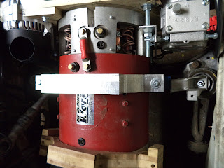
The BMW 325i does not allow for much space between the bottom of the Warp 11 and the car frame, thus it was decided to use a 3/8 in x 1.5 inch fabricated steel strap (Picture DSC0041). The support strap was painted and a 0.125 inch high temperature silicone gasket was bonded to the inner surface.
Although the bottom support strap was incorporated into each design, three different upper motor mount designs were fabricated as wooden prototypes. This blog entry will focus on one design that was fabricated from an aluminum billet.
Picture DSC00015 demonstrating a trial fit of one of several wooden prototypes. Making the top surface parallel to the base of the car provides a possible mounting surface. The side mounting surfaces, perpendicular to the base of the car, provide points of attachment for a short adapter to connect directly to the OEM engine mounting studs that are bolted to the frame of the car:
A slab of 1.75 inch x 15 inch x 18 inch Aluminum 7075 aircraft alloy was purchased on EBay ($180) and it was machined in the shop using a rotary table mounted on a Bridgeport vertical mill.
Picture DSC00263 showing brother George carving the initial grooves in the plate using a rotary table mounted on the Bridgeport.
Picture DSC00304 showing the preliminary cuts that are nearly thru the aluminum billet. A 0.25 inch plywood sheet was then inserted under the piece prior to the last penetrating cuts.
DSC00314 showing the final machined piece just prior to sectioning into two identical motor mounting adapters.
DSC00322 showing the top aluminum motor mounting adapter bolted to the bottom fabricated steel support strap. This was the first time using a Bridgeport mill and only 16 hours was required for the fabrication process!!
Picture DSC00324 of the installed upper and lower motor mounts. Note that the wooden prototype shown at the bottom of the picture is for reference only. The top of the picture partially shows a prototype accessories plate that includes at the top left, the OEM BMW alternator, and at the top right, the OEM air conditioner compressor.
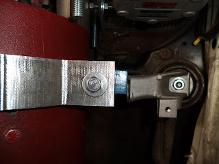
Picture DSC00325 with the further band saw shortened BMW OEM passenger side engine mounting bracket in place. Two mounting plates will next be fabricated. One plate will be bolted to the aluminum side surface, and the second plate will be welded to the BMW mounting bracket (at the right).
Picture DSC00327 of the driver side motor mount. The black duct at the bottom of the picture is the back end of the OEM BMW alternator that has been mounted on a prototype accessories plate.
Although the mounting holes will be predrilled in the plates that are bolted to the sides of the aluminum billet, the correct location for the mounting holes in the modified and welded OEM mounting adapter will be determined only after trial fitting of the two plates together in the car.


No comments:
Post a Comment