Saturday, January 7, 2023

Mounting the Water Cooled SME Controller directly to the Hyper9 AC Motor (Version 2 Bracket)


DSC01489 showing the motor resting in the NetGain cradle.  If the cradle is then mounted on a dolly, it can be moved around the shop with ease.


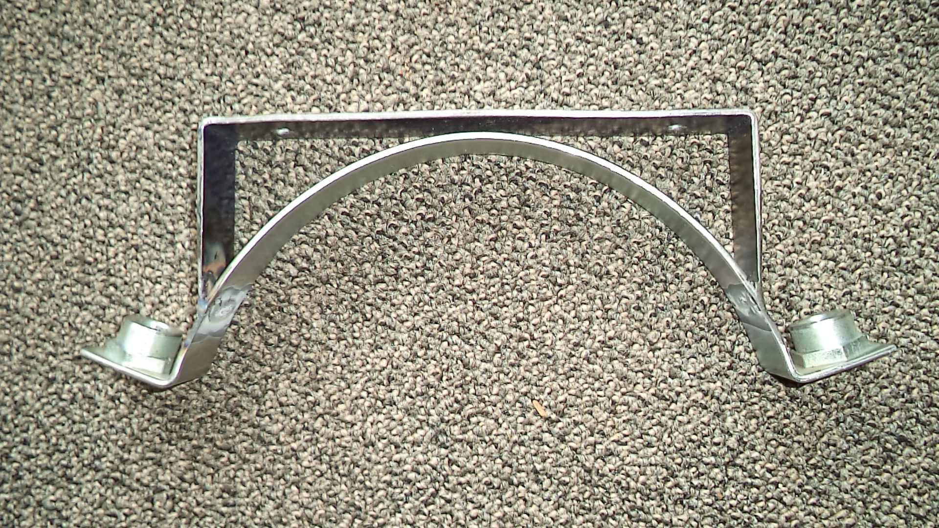
DSC01398 showing the Version 2 welded bracket.  The steel bracket was fabricated from a piece of 12 gauge HR metal plate that was cut to 14" x 1.25".  The length of each leg is 4.75" and the horizontal surface is 7.75" (the SME controller base is 6.25" x 8.25").  This bracket is version 2.

Edited 3/23/2023


DSC01402  Closeup of the welded bracket on the top section of the cradle.  Note that the maximum horizontal surface is about 7.75".  The 3" OEM supplied bolts can no longer be inserted from the top and must now be inserted from the bottom along with an additional nut at the top.  Alternatively, if the cradle is slightly bent outward, then the bolts can be preinstalled on the bench, and the cradle can then be gently bent back to its original configuration.  (1/26/23) The nuts are 1/2"-13 and the bolts are 3.5" long. 


DSC01399 showing the attached Controller mount on the body of a NetGain Hyper9 AC motor.  The way that the cradle is factory designed, the line of draw for the bolts is inward toward the midline.  A better design would be to have the bolts of the cradle vertical.  This would allow for a maximum mounting surface and easier assembly.


DSC01493 with both welded cradles (version 2) attached.  The useful distance between the mounted brackets is about 19.5 cm.   


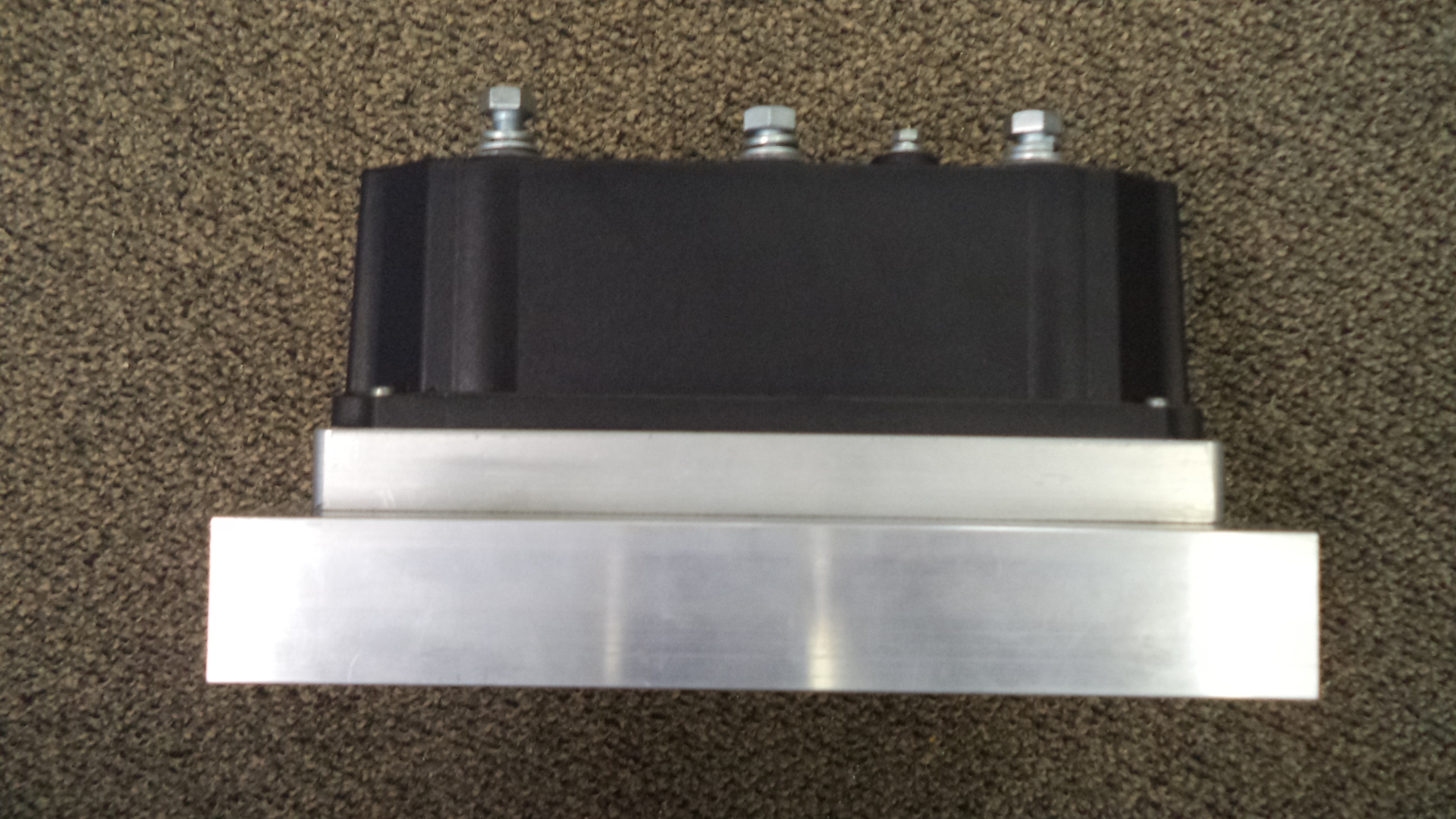
DSC01406  End view of the welded cradles and the water cooled SME controller both directly mounted to the cradle.   The controller and chiller plate weight about 9.4 pounds.  Vibration damping mounts of 0.625" diameter (1/4" - 20) with stud and inserts were purchased (McMaster 93945K11, $5.82 each) that are rated at 15 pounds each.  The downward directed stud thread length is 1/2".  The upper female threaded portion is 1/4"-20 and 0.25" deep.  Zinc plated steel threaded rods (McMaster 95475A551, 2.25" length at $19.60 for 50).  7/8" long coupling nuts were used to secure the controller to the studs to allow easy socket wrench access.   No mounting plate in this assembly.

The next generation mounting plate should be min. 0.25" taller to allow for air cooled fins to have adequate clearance above motor housing.  The upper surface of the steel mounting surface should be min 22 mm from highest point (center of motor).

Water cooled SME controller on a mounting plate.

In both configurations below, a wiring harness will be needed that has tight bends.  Possibly a braided strap or a flex braid or a copper buss bar or buss bar ground braid or a pair of custom mechanical lugs that are joined with a flexible 2/0 jumper. 


DSC01497 with the SME controller located for power cables on the side.  This 6061 plate is 0.125"x7.75"x10.375".  Three plates were cut from a scrap piece 20" x 20" x 0.125" plate that was purchased for $29.01.  


 DSC01498  The 6061 plate (0.125" x 7.75" x 10.375") with the SME controller mounted with the power cables on the side. 


 DSC01501 with the SME controller located for power cables at the end.  This larger 6061 mounting plate (0.125" x 9" x 10.5") is wide enough that the SME controller can be rotated so that  the terminals align with the motor terminals.   The connections in this orientation are misaligned.  The U1 controller terminal goes to W on the motor, the V1 of controller goes to V on the motor, and the W1 of the controller goes to  U on the motor.  This alignment results in the motor direction being reversed.  A software alteration will be possible to wire in this fashion.


DSC01502 with the SME controller located for power cables at the end.

DSC01504 side view of the SME controller oriented for power cables at the end.  In this picture, larger 1" vibration damping mounts of 1" diameter were used. (McMaster-Carr  93945K117 at $8.94 each).  They are rated at 40 pounds each. 


Friday, July 1, 2022

Hyper9 Motor Support and Cradle - Version 1

Purchased a Stainless Steel motor cradle from NetGain Motors (part MC-H9225 for $112.50).

The pair of galvanized steel clamping bolts are 3.5" long and 1/2"-13 coarse thread (3/4" socket head).   Stainless Steel replacement bolts for $3.13 each are available from McMaster-Carr ( https://www.mcmaster.com/93190A726/ ).

updated 7/15/2022


DSC01363 Side view of the 9" ID motor cradle. 


The engineering drawing for this cradle can be found here:

https://www.go-ev.com/PDFs/MC_H9225_Information.pdf  

updated 3/3/2023


DSC01366 Closer view of 1/2" bolt assembly of the cradle.  The bottom of the cradle uses a pair of steel narrow-base weld nuts, 1/2"-13 thread size  (McMaster 90594A033, 25 units for $22.27).  It is important to align the bolts correctly to engage the lower threads and not cross thread them..  The top fitting is just a thick washer that is crimped fit to the top of the cradle (no threads).

Updated 2/17/23


DSC01366 Top view of the cradle showing the metal band.  The steel band is 1.25" wide and when covered with the rubber bushing the total width is 1.50". 


DSC01366 Bottom view of  the base of the cradle.  The metal band is 3 mm thick and 37.75 mm wide (about 1.485").  The pair of mounting holes have a diameter of 0.59" (15.0 mm) and either a  9/16" or 14 mm bolt will pass freely.  The mounting holes are 215 mm (about 8 7/16") center to center.


DSC01375 Picture showing a Hyper9 body clamped within the NetGain support Cradle.


Tuesday, June 28, 2022

Air Cooled Hyper-9 Chill Plate

If one is not interested in installing a glycol/water based cooling system along with the Hyper9 controller, then an air based cooling system may be an alternative.  If properly constructed and mounted directly over the Hyper9 motor, then accompanied with a forced air fan, it may also be possible to gain some cooling for the motor at the same time.

In review, the dimensions of the Hyper9 controller are 8.25" by 6.25", and the overall length of the Hyper9HV is about 14" with a maximum width of  9".

Several sample chill plates were purchased and modified and they are shown in picture DSC01355.  All of these chill plates are extruded 6063 alloy and they are manufactured in the USA.  The sizes shown are 14" x 8.5" (top left), 14' x 7.25" (top right), 7.25" x 9" (bottom left and center left), and about 8.5" x 7" (bottom right and center right).  All of the chill plates have a fin height of 1.0" and an overall thickness of about 1.30".


DSC01355 showing the selection of air cooled chill plates that were selected for testing.


DSC01358  with a paper template of the controller on top of the fins of the chill plate.  These fins run perpendicular to the long length of the controller.  The picture shows the template on the same side as the fins, but actually the controller would be on the flat opposite side.  We plan to also use a heat transfer paste between the flat surface of the controller and the flat surface of the Chill Plate (to be reported later). 

updated 7/15/2022


DSC01360 side view of the mounted 8.5" x 7" chill plate shown in picture DSC01358 in which the fins run perpendicular to the long length of the controller.


DSC01359 with a paper template of the controller on top of the fins of the 7.25" x 9" chill plate.  The fins run parallel to the long length of the controller.


DSC01361 side view of the 7.25" x 9" chill plate shown in DSC01359 showing the controller mounted to the face of the chill plate and with the fins running parallel to the long length of the controller.


DSC01362 top view of the 14' x 7.25" chill  plate with paper template of the controller in place to demonstrate the range of location that is possible.  This plate is equivalent to the 7.25" x 9" plate shown in DSC01359, but it is longer and it allows for greater variation in the placement of the controller.   


DSC01357 of  a chill plate that is 14" x 8.5".  This size can allow for a pair of controllers to be mounted on the same surface.  The fins run perpendicular to the long dimension of the controller.


Wednesday, August 11, 2021

NetGain HyPer 9-DHV Motor Controller

 A Hyper9HV controller was improperly wired by an end user resulting in the failure of an internal capacitor.  The four T10 Torx screws that secure the black plastic housing to the Aluminum base were removed and the controller opened so that some pictures could be taken of the internals.  SME  S.p.A. has very efficiently designed this unit and it is much more compact then the Soliton DC controller that was previously used to control the Warp 11.   updated 8-20-21


Picture AIMG-0012  Top view showing the pair of cable connectors (upper left and middle far right) and the -B and +B (center) terminals and the U1 and V1 and W1 terminals at the bottom.  The +B pre-charge is the small terminal at the bottom to the right of center.  updated 8-19-21


Picture AIMG-0016   End Side View showing the small cable connector (K3) at the top left.  The IGBTs are at the bottom and they appear to be directly mounted to the Aluminum base.  The Aluminum heat sink base is 160.41 mm x 210.20 mm x 18.23 mm thick.  updated 9-18-21


Picture AIMG-0013A  Long Side View adjacent to terminals U1, V1, and W1.  Note that each terminal is provided with red o-rings that  provide a dust seal between the terminals and black plastic housing.


Picture AIMG-0015  End Side View showing the main cable connector (K1).

Saturday, December 14, 2019

NetGain HyPer 9-DHV Motor Controller and Kit.


The product description for the HyPer 9-DHV controller is as follows:

Type:  ACX1T50000100
Model:  AC-1X 120/144 V 500 A  112 SWS
SN:  9735730003

The controller can operate in the range of 90 to 180 volts.  This 1992 BMW 325i build will operate at a nominal 144 volts.


DSC06595 Top view of the controller.  Terminal bolts are in the plastic bag.


DSC01163 Detail picture of supplied hardware which includes five M8-1.25x20 hex head bolts (torque to 15Nm max)with washer and lock washers.  These are used for the -B, +B, U1,V1, and W1 terminals.  Also included is a M4-0.7x10 bolt (torque to 2.5Nm max)with both washers.  This is used for the +B pre-charge terminal. The outer diameter of the M8x20 Zinc plated bolts was measured to be 7.82 mm. 
Lock washer ID =  8.29mm, flat washer ID = 8.44mm.     Updated 6-22-2021


DSC06598 side end view of controller.  The black plastic housing is attached to the Aluminum heat sink (base) with four T10 Torx bits (two are shown in the picture).  Updated 9-15-2021


DSC06597 of the 35 pin connector.

Edited 6/8/2023

DSC01891 showing a dust cap that was printed for the K1 port on the SME AC-X1 (or X144) Controller/Inverter.   Ken (a member of the electric auto club FVEAA) made the cap with a Ender Pro 3 and he has posted the file here:


The cap fits perfectly.  We added a few small drops of bathtub Silcone sealer on the inside edges of the cap to further increase the grip of the cap while we are working with the controller.   


DSC06601 showing the mounting holes at the corners of the base of the controller's Aluminum heat sink.  The mounting holes are 6.5 mm diameter and are 197 mm and 147 mm center to center.

The kit purchased from NetGain included the following:

HyPer 9-DHV 3 phase motor  (pictures shown previously in 9/24/19 blog posting)
Hyper-Drive X144 controller  (for up to 144 volts operation) Serial number 9735730003
500 Amps with Standard Ampseal Wire Harness
Gigavac GV200PA-1 contactor
HTS: 8501.32.4500


DSC06593 of the components included in the kit in addition to the motor and controller.  In the center of the picture is the bag of terminal pins for the motor encoder and motor thermistor plugs attached to the motor.  Starting at 12:00, the black plastic 3 phase terminal cover, pre-charge relay, Gigavac main contactor relay, computer cable (bottom right), USB to cable, and wire cable bundle with red Ampseal 35 pin connector.


DSC06596 Picture of the 35 pin Ampseal connector.  Updated 9-18-2021

A full description of how the crimped wires are installed in the AMPSEAL connector can be found here:   https://www.youtube.com/watch?v=uXTkm_XV2OY

It appears that this video (  https://www.youtube.com/watch?v=v157tIIQGEc ) discusses the crimping tool used for the AMPSEAL 16 contacts.  Updated 10-5-2021


                                        (picture of Gigavac to be added)

DSC0   of the Givac 500 amps main contactor relay.


DSC06677 Top view of the pre-charge relay.


DSC06678  Side view of the pre-charge relay.

The HyPer 9-DHV user manual can be found here:

https://www.go-ev.com/PDFs/HyPer_9HV_IS_User_Manual_REV08.pdf 

Thursday, December 12, 2019

Chiller Plate Fabrication Part 2- Machining Steps


DSC06687 Picture showing the Aluminum chill plate version 1.0 after the majority of the CNC work had been completed.


DSC06686 During fabrication a small layer of Aluminum was left on the bottom of the plate which when eventually removed provided a brilliant smooth surface on both the top and bottom faces of the plate.

The final chiller plate dimensions match the controller base dimensions and they are described in the previous post.


DSC06602  The 1.25" wide channels allow for good flow and contact surface.  The final weight of  chill plate version 1.0 was 708.23 grams.


DSC06627 Showing the internal view of the 0.125" NPT inlet and outlet ports on the side of the chiller plate.  updated 2/7/2020   Pilot holes drilled with 0.332" (Q) drill ($7.19) and tapped with 1/8-27 NPT tap ($6.19).  updated 3/18/21  The center to center spacing was initially 38.1mm,  but later chill plate version 2.2 provided an increased center to center distance of 50.8 mm to accommodate larger footprint 90 degree elbow fittings.  updated 9/7/21


updated 3/18/21
DSC06628 Gasket adhesive that was used to secure the Chiller Plate to the base of the controller.  One source is Advanced Auto Parts part number 22072 at $4.49.  EVWest indicates that white silicone should not be used as it degrades over time. 

To mount the chiller plate to the controller, the bottom surface of the controller and the top surface of the chiller plate are cleaned (brake cleaner or solvent) and then Gasket Maker is applied to the top  surface of the chiller plate.  The bolt holes are aligned and the two parts are clamped together for curing for 24 hours.  Any excess silicone can then be trimmed from the sides.  During fabrication of the chiller plate, if a small beveled edge is machined onto one of the top outer edges of the chiller plate, the bevel can allow for insertion of a chisel so that a mallet can then be used to separate the two parts later if needed.

Alternative Chill Plate Design - Faster Flow Design

The inlet inner diameter of a 1/8" NPT hose nipple is 0.307" (thin wall schedule 10) and 0.269" (standard wall schedule 40).  Thus for a schedule 40 pipe fitting, the cross sectional area is 0.227 square inches.  This cross sectional area will define the flow rate at a given inlet pressure.  Once the cooling fluid enters the plate, the larger cross sectional area (rectangle 1.25" wide and 0.50" tall, 0.625 square inches ) results in a flow rate that is only 36.3% of the inlet flow.  It is not known how much heat must be removed from the controller when it is under full load.  It is possible that a different design with only 0.75" channel width and the same 0.50" depth, will not have any material impact upon performance, but we will make one and test it.  This design is much simpler, although tedious to fabricate, when manually operating a Bridgeport.


DSC06698 Showing the smaller 0.75" width channels in an alternate design chill plate version 2.0. The final weight of this design is 708.41 grams.


DSC06697 Edge on view showing the input and output NPT threaded holes for version 2.0 at the far side and on this plate the addition of two extra threaded ports holes at the front edge for optional sensors.
updated 2/7/2020
updated 9/7/21

DSC06782 Edge on view showing placement of 0.125" brass plugs installed into sensor ports of version 2.0 with sensor.
updated 9/7/21


DSC06795  Multiple copies of these plates version 2.0 were fabricated and they are available to others by contacting William at sales@narchem.com .

updated 2/19/2020

DSC06792  Picture of McMaster Carr (part 5346K13, $1.19 ea.) straight brass barbed for 1/4" hose ID that was used when the center to center holes was only 1.0" (chill plate version 2.0).   The ID of the straight fitting is 0.18".
updated 9/7/21


DSC06794 Picture of McMaster Carr (part 53525K11, $2.67 ea) of the 90 degree elbow brass barbed for 1/4" hose ID that was used when the center to center holes was 1.50" (chill plate version 2.1) and there was additional space for rotation of the fitting during installation.  The ID of the 90 degree elbow is 0.18".
updated 9/7/21

Tuesday, October 1, 2019

Chiller Plate for Hyper 9-DHV motor.

Chiller Plate for HyPer 9-DHV

The three phase controller designed for the HyPer 9-DHV has an operating temperature range of -40' C to +95' C.  At 80' C the controller will enter Thermal Cutback Mode, and at 95' C, the controller will shut down in an effort to save itself.   The manufacturer recommends a chiller plate for any application that exceeds 200 amps of continuous use.  A chiller plate can be purchased at the same time the motor is purchased or added later as needed.  Our plan is to test the limits of the HyPer 9-DHV motor, so we are confident that we need a chiller plate, and we will connect it to a circulating pump and a small radiator.

The Aluminum 6061 chill plate (DSC06602) version 1.0 dimensions exactly match the controller base dimensions and they are 210 mm x 160 mm.  The centers of the mounting holes (6.5 mm) for both are located at the corners  of a rectangle that is 197 mm x 147 mm.  All internal walls are 0.125" (3.175 mm).  The overall chiller plate is 0.625" (15.9 mm) thick with channel depths of 0.50" (12.7 mm).   The inlet and the outlet ports are both  0.125" NPT.   Prior to machining the Aluminum plate is about 1487 grams and when completed it weighs about 713 grams.

Edited 10/21/19,
Edited 12/13/19


DSC06602 picture of the top view of the HyPer 9DHV Chill Plate. Version 1.0


DSC06603 picture of the 0.125" inlet and outlet ports for the Hyper9DHV chill Plate.  Version 1.0

The four mounting holes in the chiller plate align exactly with the four mounting holes of the controller.  After application of an RTV type of sealant, the chiller plate is bolted cavity upward between the base of the controller and the mounting platform located directly above the motor.