Friday, August 31, 2012

Modifications of Original Transmission Adapters


                                                              Picture DSCN0848-2
Although this modification does not effect the performance of the adapter, it was decided to improve the cosmetics of the motor face side by using the mill and running a 4" diameter fly cutter over the full face of the plate.  Three separate passes, each time removing 0.001" of metal, yielded a surface that, after a final light Scotch Brite application, demonstrated a very pleasing nearly mirror like finish.  Compare to Picture 4790 below (originally posted on 7/28/2012).  To compensate for this reduction, the centering ring was also thinned by an equivalent amount.  The outer surface of the spacer ring was also turned in the lathe to improve its appearance.  A total of about 4 hours was spent to achieve these results.


                                                                      Picture 4790
                             Picture showing the original transmission plate adapter as received.


Thursday, August 30, 2012

Warp 11 Motor Face Modification

The hub adapter as supplied by Pioneer Conversions in Lemont was designed to fit the stock Warp 11 shaft without any modifications, and dimensionally to work with the aluminum adapter set that was also supplied by their contractor.  By contrast, the compression hub adapter that we are developing is designed to utilize as much shaft length as possible.  To allow this newer design, it was necessary to relieve a portion of the end plate of the Warp 11. 
 
To achieve this, the motor was stood on end and a Vice Grip pliers was attached to the opposite end of the shaft over a protective layer of duct tape (don't want to scratch the metal shaft).  The 8 cap head bolts were then removed from the motor and the end plate easily removed to reveal both the internal motor bearing and the cooling fan.


                                                                  Picture DSC0481
Picture showing the placement of the vise grip pliers to stabilize the shaft during removal of the end plate.


Picture DSC0844
Picture showing the motor internals after removal of the end plate.  Motor bearing is visible directly next to the black cooling fan.


                                                                   Picture DSC04846
Picture showing the original Warp 11 drive end motor face after removal from the motor and prior to modification.


                                                                 Picture DSC04855
Picture showing closeup of the original Warp 11 motor face at the drive end prior to modification. The motor face as supplied by NetGain has a specification 3.997-4.000 inch diameter (ours was delivered with 3.999) and the pilot boss specification is about 0.5 inch high.  The outer diameter of this elevation inserts into the donut spacer of the transmission adapter, which should be slightly above 4.000 inches. 


                                                                  Picture DSCN0835
Picture showing Warp 11 motor face after machining a 3.2 inch diameter and 0.375 inch deep recess.  We needed about 0.25 inch clearance for our design.  The purpose of this recess is to allow the 1.57 inch long concentric adapter to fully grip the shaft without falling on the chamfer at the end of the Warp 11 shaft.


                                                              Picture DSCN0835
Picture showing a closeup view of the machined recess added to the face of the Warp 11 drive end motor face.  Even after our modification, the motor plate has 0.752 inches thickness to support the bearing.  We estimate that only 0.25 inches might be required to support the bearing properly.


Saturday, August 25, 2012

Comparison of Adapter Styles (Keyway versus Compression)

The original key way style adapter has been picked up and we can now compare both designs side by side.

The primary difference between the two different style adapters is that in the case of the key way style adapter, the hub is retained by the inserted key that mates the key way of the shaft to the key way of the hub adapter.  When the set screws are tightened one might anticipate that the hub would be pushed slightly eccentric relative to the center line of the shaft.  It is our understanding that this is a minimal amount, and that with the use of Loctite, and careful alignment and tightening, the result can be a very good alignment of the hub relative to the shaft.  This style of adapter is very common in the EV world.   But, we have also been told that there can be an element of "art" involved in putting together a very good assembly.

The compression style adapter allows for a concentric compression of the adapter around the entire shaft.  If done properly we understand that the concentricity can be made to be extremely fine.  We have been told by some key way proponents, that the concentric style also requires "art" for its success in assembly.  Our concentric style adapter design is much beefier that the key way style.  It is also a little longer and it should have greater grip on the Warp 11 shaft.

We will install both adapters and try to measure any alignment or vibration differences to try and learn which style adapter is easier for a "non-artist" first timer like myself to install.

We have take some additional pictures that show the design differences between the two styles.
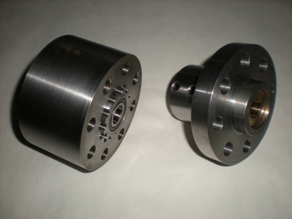


                                                                     Picture DSCN0827

Comparison view of the two styles when viewed from the flywheel side.  Note the ball bearing on the left adapter, and the bronze bearing on the right adapter.


                                                                      Picture DSCN0829

Comparison view of the two styles when viewed from the motor side.  The left side adapter has a step machined into the face.  In future builds the depth of this step may be increased to further reduce the weight of the overall adapter.  Also, note the removable compression fitting on the left.  If we remove the compression sleeve and then machine out the inner diameter of the outer aspect of the hub  (see Picture DSCN0815 in the 8/24/2012 blog posting for a better view of the opening ), we can then incorporate a larger compression fitting if we are working with a larger shaft diameter on the motor.  

We now have several of these compression clamps that are designed for the Warp 9 and the Warp 11 (ie., 1.125 inch diameter shaft) available on the shelf for other builds.  Contact us if you are interested. 

The adapter on the right clearly demonstrates both the key way, and the curious, slightly raised lip, around the shaft area.  The intention by that machinist was perhaps to obtain the maximum grip on the motor shaft. 

Update: 9/13/2012

Wrong!  When visiting with Pioneer Conversions, they indicated that the purpose of the elevated lip is when the clutch pedal is depressed in the car, the action finally transmits pressure to the flywheel (and thus the armature).  This pressure physically displaces the armature into the motor face until the lip bottoms out on the center hub of the bearing.  Very interesting !


                                                                        Picture DSCN0823

Comparison view of the two styles when viewed from the flywheel side at an oblique view.  We are considering removal of some additional metal on the outer diameter of the compression adapter in an effort to further reduce its mass.


Friday, August 24, 2012

Compression Hub Adapter has Arrived ! !


                 Great news !  No, astounding news ! The new compression hub adapter design has   arrived and it is really sweet.  It is designed to clamp around the entire shaft in a more or less uniform fashion, and we anticipate that it will not demonstrate the same lateral movement that one might expect with a key way adapter that is secured on only one side with set screws.
 
The pictures below show the overall design, and the stepwise assembly of the adapter parts, on a precision shaft that was mounted in a lathe.  The assembly was then measured for facial and radial travel when slowly rotated.  Our machinist is making a total of four of these units for our first production run, and we hope to be able to offer some of these adapters either thru this blog or on EBay. 


                                                                  Picture DSCN0814

The picture above shows the flywheel side of the adapter.  There are 8 outer perimeter holes for the bolts that will attach the flywheel.  The smaller (and inner) holes allow for the insertion of a hex key to tighten the compression sleeve clamp to the shaft after it is inserted on the opposite (motor face) side.


                                                                   Picture DSCN0817

Picture now showing the flywheel face of the adapter after the ball bearing has been pressed in.  The center of the ball bearing will function as the pilot sleeve for the tip of the transmission shaft.  
Edited 12/23/2021
The center lubricated Ball Bearing, Sealed, Trade No. 6002-2RS, for 15 mm Shaft Diameter is McMaster Carr part # 5972K83 at $9.17.  The bearing has a 32 mm OD and it is 9 mm wide.  Maximum speed is 13,300rpm.   

Edited 5/12/2023

The original hub was manufactured using 1144 free machining steel and for this project a piece of rod stock was chosen that after machining, resulted in an adapter with 3.744" diameter and 2.473" height.

A good survey of types of readily available steels can be found online in the McMaster-Carr catalog.  Type into the McMaster search engine,  "types of steel", then at the top of the page, click on "About Carbon Steel, Alloy Steel, Spring Steel, and Cast Iron,   more", and a table of choices is presented.


                                                                   Picture DSCN0820

Picture showing the test insertion of the bolts that will secure the flywheel to the adapter face. 


 Picture DSC00877 showing a sheared M6-1.0 x 30 bolt at 6:00.  This will be center drilled and extracted.er

updated 12/14/20


                                                                      Picture DSCN0815

                       Motor face side of the hub adapter prior to installation of the clamp adapter (B-Loc).


edited 5/16/2023
DSC01723 showing both sides of the Fenner Drivers B-LOC keyless bushing, 1.125", part # T122102.  ($100.84 each from BDI , 630-595-9034).


edited 5/16/2023
DSC01784 showing the taper of the insert on the right side and the internal aspect of the B-LOC. 


edited 5/16/2023
DSC01786 of Instructions included with B-LOC.


                                                                      Picture DSCN0819

edited 5/16/2023
                 Motor face side of the hub adapter after insertion of the B-Loc keyless bushing.  When tightened on the motor shaft to 12 ft-lbs torque with hex keys from the other side, the vertical space at 12:00 nearly disappears.  

Edited 12/23/2021
The internal coupling was sourced from Fenner Drives here :  https://www.fennerdrives.com/b-loc/_/B-LOC-B112-1-1/8/?=

It is a B-LOC and as of this edit they are priced at $113.74 under part number B-Loc-B112-1-1/8".

Here is a 360' view animation:

 https://www.fennerdrives.com/_resources/_global/media/360/B112/fvx.B122100/fvx.B122100.html  


                                                                     Picture DSCN0809

After insertion of the clamp adapter, the adapter was slid onto the precision simulated motor shaft that was mounted in a lathe.  The cap head bolts were then tightened thru the smaller holes on the face of the adapter and the run out of the face of the adapter was measured to confirm that the adapter face was perpendicular to the shaft.


                                                                      Picture DSCN0811

After attaching the hub adapter to the shaft that was secured and precisely centered in the lathe, the Aluminum racing flywheel was then bolted together and the axial and facial run out was measured.


We will next mount this new adapter and flywheel on the Warp 11 motor to test for vibration under power.  The three castings described in the August posting are at the machinist and we are told they will be ready next week.

The original key way hub adapter and motor/transmission adapter plates which were received and then described on this blog on July 28, 2012, are being refined at the machinist.  We anticipate that they will also be delivered to us next week.

After both designs are on site, then we will compare the designs to learn if there are measurable differences in the performance of each.

Stay tuned.


Thursday, August 16, 2012

Foundry Adapter Plate has Arrived


The cast Aluminum prototypes have been returned from the foundry.  We had three raw castings made in case there are other EVers who are interested in obtaining. an adapter from us in the future.  The next step is to send the castings to our machinist so that he can prepare the 4.000 inch center hole, machine the opposite faces parallel, and then  accurately drill the remaining bolt and dowel pin holes.


                                        Picture DSCN0798, raw casting showing motor mounting side.


                                         Picture DSCN0799, raw casting showing transmission mounting   
                                         side  The center will be machined out to 4.000 inches for mounting
                                         of the Warp 11.

Our part time machinist is still working on our compression style shaft hub adapter.  We hope to have a prototype and some pictures within the next week.  It is our intention to test both adapter systems (keyway versus hub clamp and machined from plate stock versus foundry casting) and compare their performance in service.