Monday, July 7, 2014

Installation of the Shift Linkage to the Getrage transmission


All of the initial testing of the Getrag transmission has been conduced without the gear shifter being installed and in the next step of testing it is hoped to fully operate the transmission and shift through all of the gears with the Warp 11 energized.  To achieve this requires the following improvements:  attach the clutch slave to the transmission;  replace the brake/clutch fluids with fresh fluid;  bleed air from the clutch fluid lines;  install the gear shifter and linkages;  and fill the transmission with fresh fluid.  At that point, with the car remaining on four jacks, it should be possible to operate the transmission and run it through all of the gears at different motor speeds.

Previously a backup 5 speed Getrag transmission was purchased on Ebay that was listed as being from a 2002 BMW E46 325i.   Online research suggested that it should be identical to the transmission from a 1992 BMW.  It was decided to maintain the original 1992 transmission, but replace the shifting mechanism and shifter knob with the 2002 parts as they were in better cosmetic condition.  Sadly, after attempting the substitution, it was discovered that the 2002 arms do not fit!  Subsequent careful comparison (which should have been dome prior to initial attempted assembly!) showed the obvious reason why, they are of slightly different lengths, ugh!!


Picture DSC01510 showing the 2002 E46 shifting arm (top) and the 1992 E36 shifting arm (bottom).  Although the transmissions appear to be the same, the shifters are definitely not.  The difference was discovered when it was attempted to install the 2002 assembly into the 1992 car.  Once installed the 2002 shift knob shaft was angled forward and the shift lever bearing was pressing against the rear of the center console opening such that it would not rotate freely.  By comparison, when the 1992 shifting arm was installed, the shifting bearing was centered in the console opening, the shift knob shaft was perpendicular to the floor, and it could be moved freely in any direction..


Picture DSC01514 with the 2002 (top) and the 1992 (bottom) straight selector rods also of different lengths.

Installation of the shifting mechanism proved to be a lengthy project,  but after multiple attempts and a lot of practice, it was learned how to rapidly install or remove all of the components. 


Picture DSC01345 showing the center console still in place, with the rubber shifter covering removed (left center).  The black drive shaft is visible through the circular opening at the right center.  The shifter mechanism passes directly under the circular opening and the shift knob shaft passes up through the round hole, and then the  rubber shifter covering, and finally the gear leather cover (boot).

It was not possible to access the top of the transmission from within the cabin.  The motor mount bolts were removed and the front of  the Warp 11 raised with a floor jack.  The drive shaft center support bearing assembly was disconnected from the car frame to allow the drive shaft to lower significantly away from the console area.


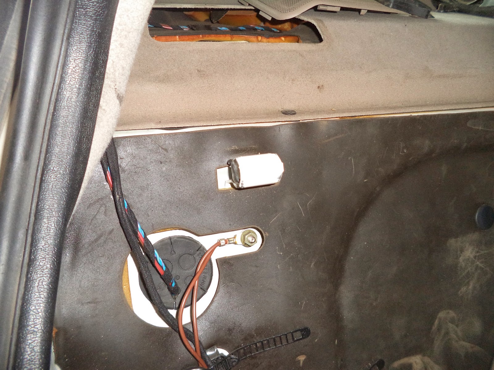
Picture DSC01512 showing the open area created after the drive shaft was lowered away from the console dome.

The challenge is to connect the transmission to both the shifting arm (part 1 in diagram 1) and the straight selector arm (part 9 in diagram 1).

Parts diagram


Diagram 1 is a parts diagram from the RealOem.com website (a phenomenal resource for parts and diagrams) showing an exploded view of all of the Gearbox Shifting Parts.  See:   http://www.realoem.com/bmw/showparts.do?model=CB33&mospid=47498&btnr=25_0013&hg=25&fg=05


Picture DSC01501 demonstrating the shifting arm (center silver) and the straight selector arm (bronze color to the bottom left) both attached to the 2002 Getrag transmission.


Picture DSC01504 showing (view from under the car) the bottom of the console dome and the  original rusted shifter arm bearing being held by a welded bracket on the car frame.  The shifter bearing was removed by inserting a screwdriver between the steel cylinder and the bracket and separating the two parts.  This bearing is a metal tube with a rubber molded insert that slides over the tail section of the shifting arm.  Its purpose is to hold the shifting arm horizontally and allow for slight rotation and slide as the shifter is moved.


Picture DSC01505 after removal of the shifter bearing.  There are two slots on opposite sides of the shifter bearing that allow the metal tabs on the bracket to snap into place.


Picture DSC01507 showing the 1992 shifter bearing on the left and the 2002 bearing on the right. Note that the metal ring is not contiguous and the molded black rubber is visible in the center. This may allow for some compression of the metal cylinder during installation.  The newer shifter bearing was used to replace the rusted one on the left.


Picture DSC01509 end view of the 1992 shifter bearing on the left and the 2002 bearing on the right.  The center opening allows for support of the rear end of the shifting arm as well as permitting both rotational and lateral movements of the arm during the shifting process


Picture DSC01513 after the shifting arm was inserted into the bracket on the top of the Getrag and the retaining bolt (part 3 in Diagram 1 above) was inserted and locked into place.  It was necessary to elevate the tail of the transmission and the drive shaft, as required, to fit the shifting arm and straight selector rod into place.

 
Picture DSC01500 showing the retaining bolt being inserted into the transmission bracket and the shifting arm bushing.


Picture DSC01502 showing the shifting arm installed and locked into place with the 10mm x 40mm retaining bolt (top right) snapped onto the transmission frame.

The most challenging task for the installation turned out to be the pressing of the shifting bearing back into the bracket at the top of the console dome.


Sunday, July 6, 2014

1992 BMW 325i Rear Seat Removal


The ICE initially had its fuel pump and gas tank located under the back seat bottom cushion.  To gain access for servicing, it was necessary to lift the leading edge of the bottom cushion upwards.  The cushion will suddenly pop up and it can then be removed.


Picture DSC01588 showing one of two steel brackets that snap into the bottom of the seat cushion.  This picture is of the passenger side adjacent to the location of the power cables.

To gain access to the rear bulkhead that separates the cabin from the trunk requires the removal of the upper portion of the back seat.  There are two steel brackets that project from the top of the car body at each corner of the back cushion.  There are four openings at the bottom of the rear seat into which corresponding pins on the bottom edge of the back cushion will insert.  Thus, to remove the seat, first pull toward the front of the car at the top of the seat by each of the rear door windows.  The top will then pop out.  Then lift the seat upwards and forward to disengage the two sets of pins at the bottom of the cushion.


Picture DSC01582 showing the steel bracket (white plug shape in center of picture) that is welded to the rear bulkhead.  This view is on the passenger side.


Picture DSC01581 showing the corresponding socket  that is integral to the seat. This socket snaps over the bracket shown in Picture DSC01582 above.


Picture DSC01583 showing the welded steel slot (white rectangle slightly left of center) that is located at the rear of the seat.


Picture DSC01591 showing one of the two heavy steel pins (left and copper colored) and one of the two light duty steel pins (far right at the corner) that are integral to the seat.  The heavy duty pin slides into the socket shown in Picture DSC01583 above.

Since many of the electrical systems within the cabin had been disconnected, removing the rear seat required some thought as the rear doors were locked and the headrests were in the way.  By reclining the front seats full backwards it was possible to slide the back seat forward and then out of the car.  The doors were apparently in "child proof" mode as neither the buttons nor the door handles would open the doors.  Later it was finally remembered that when the 12 volt car battery is turned on, then the driver's door key will open all of the locks at the same time!


Picture DSC01285 showing the removal of the top portion of the rear seat.


Picture DSC01592 showing the rear view of the back seat after it was removed from the car.


Saturday, July 5, 2014

1992 BMW 325i Front Seat Removal

To gain access to the floor area and search for a route through which the rear battery pack power cables can pass, required the removal of the seats.  Each of the front seats of this 1992 BMW E36 325i are secured at four locations.  Two M10 nuts secure the base to studs welded to the floor at the front, and two M10 bolts attach to threaded openings in the floor at the base at the back.  Although the seats have manual attitude adjustment, both front seats have embedded electric heater elements and the connection cables on the underside of the seat must be removed prior to extracting the seats from the car.


Picture DSC01297 of the passenger seat in full back position revealing the plastic nut cover.


Picture DSC01299 showing the revealed a M10 hex nut  (16 mm socket for removal) that was attached to a chassis stud welded to the floor.


Picture DSC01304 showing the tilted back passenger seat with the pair of electrical cables attached to the seat.  A plastic tie-off was cut prior to being able to unplug the two connectors.


Picture DSC01313 showing the seating wires as they emerge from the carpet below the seat.   The pair of wires with blue/white and brown attach to the socket closest to the door, and the pair of wires that are yellow/white and brown connect to the socket closest to the mid line of the car.

The passenger seat was then reclined toward the back seat area, and lifted up and the base rotated out onto the door frame.  This exposed the seat belt connection which was attached to the seat with a T50 Torx bolt.  After removing the bolt, it was rethreaded back into the seat belt harness plate so that it would not be misplaced.


 Picture DSC01590 showing access gained by tilting the passenger front seat backwards and raising the chair frame onto the frame of the door.


Picture DSC01309 after the removal of the harness bracket from the seat frame.

A note of interest is that each of the bottom rails is independent of one another.  During handling it is possible to shift only one rail such that when the seat is replaced in the car, only one side is aligned with the mountings.  To correct this the seat is removed from the car, the release lever activated on the side of the seat, and then both rails pushed back until they stop, then they will be symmetrical and all of the mountings will line up.  

The removal of the seats allowed for the removal of the carpet and access to the wiring underneath.    Additionally, this action improved the overall budget for the project, as $1.58 in coinage was discovered in the process.  Sadly, all the coins were found under the driver's seat, so this represents more of a recovery process than an infusion of fresh capital, which would have been the case if the coins were discovered under the passenger seat!


Picture DSC01497 of the treasure found under the drivers seat.

Friday, July 4, 2014

Routing the Rear Battery Cables to the Motor Compartment 2.0

This posting is a continuation of the previous posting in which a route was established for passing the battery pack cables from the trunk forward to the Soliton1 motor controller at the front of the car.  This year Independence Day falls on a Friday, and thus a three day weekend presents itself for EV activity.  What better way to celebrate Independence day than to work on becoming Independent with the building of an Electric Vehicle.


Picture DSC01365 showing the BMW 12 volt battery cable as it rises up the front seat foot well and then passes into the motor compartment.  This cable is connected to what is called a battery B+ base.  This base is bolted in the motor compartment on the passenger side adjacent to the firewall.  It is essentially a junction box that distributes 12 volt battery power in the hood.


Picture DSC01367 showing the B+ junction after it was unbolted from the chassis and the covers were removed.  Notice that the trunk battery is connected to the bottom far right bolt, and the smaller red cable from the trunk battery is connected to the smaller far right bolt.  The heavy gauge red wire on the left and the black wire are the beginnings of the pathways towards the starter, alternator, instrument cluster etc.


Picture DSC01369 shows the entrance point of the battery cable into the motor compartment after the B+ junction box and the 12 volt cables were removed.  The large rubber gasket was initially against the firewall.  The battery cable had a grommet that fit into this gasket and then passed through the firewall.


Picture DSC01371 shows the rubber grommet that was attached to the OEM battery cable as it entered the motor compartment through the firewall.  This grommet was cut away in anticipation of adding two additional power cables adjacent to the 12 volt battery cable.


Picture DSC016007 view from the backseat showing the cables entering the cabin through the rear bulkhead.  The original opening was enlarged in all directions with a grinding stone.  A piece of black rubber grommet material was then added over the metal edges to protect the cables from chafing.


Picture DSC01598 of the floor of the back seat after the two new battery pack cables were coursed alongside the original 12 volt BMW battery.


Picture DSC01599 showing the floor area under the front seat and into the foot well after the battery pack cables were installed
.


Picture DSC01601 showing the back seat floor area after the ABS plastic protective cover was bolted back to the floor studs.  The entrance to the plastic at the top right was easily wide enough to accommodate all three cables.


Picture DSC01602 showing the front seat floor area after the ABS protective cover was bolted back to the floor studs. Originally the 12 volt battery cable was encased within this plastic trim (Picture DSC01315 previous posting on 6/26/14).


Picture DSC01603 showing the opening in the protective ABS plastic flooring trim piece.  The opening was not wide enough at the top for all three cables to enter the trim piece.  A desirable improvement would be to notch the top left corner of the trim piece so that all three cables could enter and be protected by the plastic piece.

Before the carpeting is finally installed, it is intended to run some shielded wires from the trunk area to the hood area following the same pathways used for the batteries.  This cable would then allow for the installation of future instrumentation and sensors without once again dismantling the passenger compartment.

The 2/0 welding cables being used here are intended for initial testing purposes only.  After the optimum cable lengths are determined, then these testing cables will be replaced with 2/0 shielded cables in an attempt to reduce unwanted electrical interferences that may be caused during normal driving conditions.