There has been discussion of the requirements for good air flow past the carbon brushes and through the body of the Warp 9 and Warp 11 motors to help cool the rotor and expel any graphite dust released by the brushes during operation. Accumulation of graphite dust within the motor has been reported to cause internal shorting of the high voltage to ground. The heat produced in an operating DC motor tends to be found at the rotor, and fast air flow along the rotor is generally the only method used to prevent motor overheat. AC motors by contrast under load tend to develop heat in the coils that surround the rotor, and traditionally those coils can be cooled by passing fluid around the body of the motor with a circulation pump and a traditional radiator.
At low RPM the axial fan that is mounted on the shaft of the Warp DC motors has limited air movement while at higher RPM much better cooling is experienced. To facilitate DC motor cooling it has been suggested that an auxiliary electric blower be used to increase the air flow at lower RPM since the blower would operate independently of the Warp DC motor speed. No information was found regarding the actual air flow that is present within Warp 11 and Warp 9 DC motors and it was elected to fabricate an Air Flow Test Fixture to measure the actual air flow at different motor speeds. The Air Flow Test Fixture could then be used to test the air flow rates of various commercial blowers and filters. The Fixture might also be useful in an investigation of the operating voltages produced by BMW mass flow air sensors.
A 55 gallon HDPE open head drum was purchased (picture DSC02326, reconditioned at $18) whose lid is secured with a steel closure ring (not pictured). For convenience during testing the heavy motor or other device can be positioned on the floor with the drum's white plastic lid secured producing an air tight seal. What was originally the bottom of the drum becomes the top of the fixture and the air flow output at the "top" would be attached to a rotary anemometer and/or a standard BMW mass air flow sensor. Different interchangeable lids could be purchased and adapted to each device under test, while the same drum body and air flow sensor(s) would be used for each test.

Picture DSC02326 of the 55 gallon open head drum.
The base of the drum was drilled with a 4.125" hole saw. A 3" PVC plastic bathroom floor drain (Home Depot, $2.98, shown in picture DSC02316), was secured to the drum base with 1/4" x 1" bolts and washers (picture DSC02332).
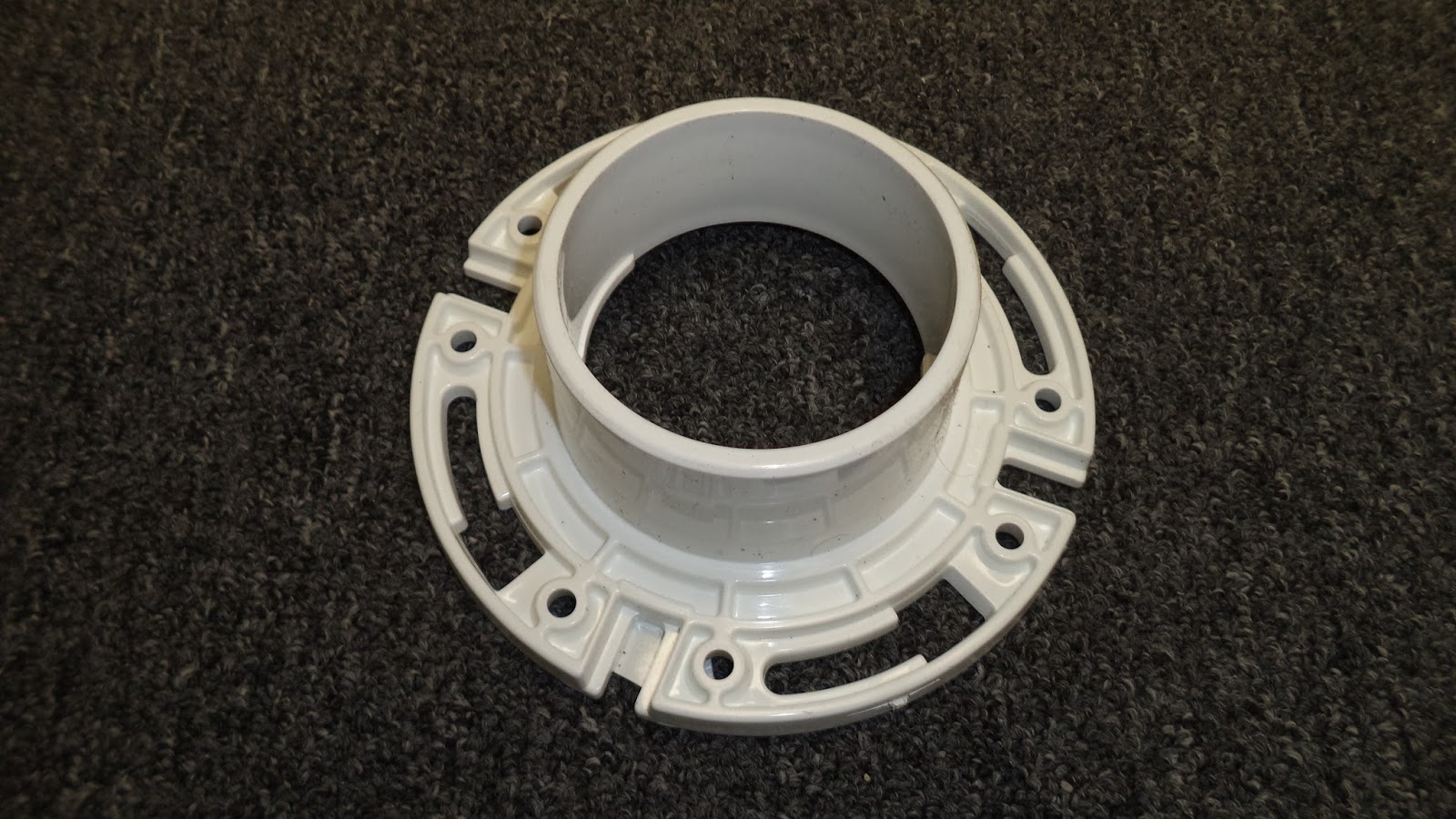

Picture DSC02332 showing the mounted 3" PVC bathroom floor drain in what previously was the bottom of the plastic 55 gallon open head drum.
The washers were later replaced with right angle brackets (Home Depot) to allow the attachment of springs to compress and hold all of the components together.

Picture DSC03692 of the angle brackets that are attachment points for mounting springs that will hold all the components together..
To secure the anemometer in place, a 3" PVC pipe section was machined out (picture DSC02312).

Picture DSC02312 of the 3" PVC pipe after machining to allow placement of the anemometer.
The outer diameter of the anemometer was about 3" and it fit snugly within the PVC pipe (picture DSC02315). An O-ring or equivalent will be added to create a tight seal.

Picture DSC02315 showing the anemometer fitting snugly within the machined PVC pipe section. .

Picture DSC02331 of the Extech AN100 anemometer mounted at the output end of the Air Flow Test Fixture. This preliminary design did not allow the addition of any other measurement devices and the slot was then extended to permit the attachment of a 3" PVC pipe coupling.
It was then decided to combine a BMW mass air flow sensor with the anemometer as part of the testing process. The BMW mass air flow sensor has an external diameter of about 3.04 inches while the inner diameter of standard 3" PVC pipe is very close to 3.00". With a Bridgeport and rotary table one end of a section of 3" PVC pipe was then enlarged (Picture DCS03768) so that the end of the mass flow sensor could be inserted. A coupling was then used to connect the upper pipe section (that held the air flow sensor) to the lower pipe section that held the Extech anemometer.

Picture DSC03768 showing the PVC pipe after it was machined to accept the mass flow sensor.

Picture DSC03767 of the design that allows for both the Extech AN100 anemometer and the BMW mass airflow sensor to be mounted at the same time. The O-ring that was supplied with the air flow sensor was retained and it facilitated the seal between the sensor and the PVC pipe. Extension springs (3/8" OD) were purchased that when half way extended had a length of about 9.25" as required in this fixture.

Picture DSC03765 showing the angle brackets and a very small key chain ring that were used to connect the spring to the base.

Picture DSC03766 showing the 3/4" S clips that were used to secure the spring to the tabs on the side of the BMW airflow sensor.
A similar fixture was fabricated using the removable lid as shown in picture DSC02334..

Picture DSC02334 showing a 3" entrance point through what was initially the removable top of the open head drum. Hose clamps and flexible rubber hose can be used to connect the device under test to the air flow test fixture. Under operation the Air Flow Test Fixture must be oriented either horizontal to the floor, or with the Fixture base elevated above the floor to permit unobstructed air flow.

Although the Netgain Warp 9 has an external diameter of 9.25" it also has terminal posts that extend an additional 1.5" from the body of the motor. Similarly, the Netgain Warp 11 has an external diameter of 11.25", with electrical posts that extend an additional 0.75". When a jumper is installed between A1 and S1 of the Warp 11, an additional 0.25" is required to allow clearance for the jumper. A smooth surfaced plastic drum lid was selected (picture DSC03862) and a 16" diameter opening cut using a hand held jigsaw.

Picture DSC03862 of the smooth drum lid selected. The black line is the cut point to produce an 16" diameter opening.
A piece of 0.5" plywood was then cut to produce a donut shaped adapter insert that is 19" OD and 12" ID. Sixteen bolts were then used to secure the plastic drum lid to the plywood. The plastic surface closely follows the surface of the plywood, but some bathtub silicone caulk was used to create an air tight seal at the interface edge (Picture DSC03866).

Picture DSC03866 of the removable end of the motor test fixture (drum lid) with an 12" diameter opening that will allow either a Warp 11 or Warp 9 to be attached using a corresponding adapter. The adapters will be described in an upcoming blog posting. .
It is hoped that by using a 55 gallon drum as a test chamber, with internal dimensions of diameter 21.75" and length 35", that enough space will be present to allow unimpeded movement of air as it is axially exhausted from the motors. If the walls of the test chamber were very close to the motors, it might be anticipated that turbulence and air flow resistance would result in erroneous air flow measurements.