
Picture DSC03798 showing a white adhesive labels that was used when measuring and marking the drill points on the aluminum. The aluminum was hard to legibly mark, and the markings frequently were smudged or rubbed off when handled. The paper allows for cleaner dimensional markings and can be drilled directly through during the fabrication process.

Picture DSC03847 showing the top side view of the battery tray.
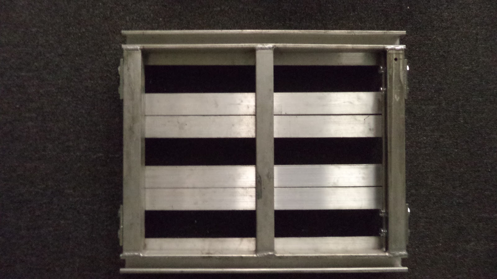
Picture DSC03805 of the underside of the battery tray.


Picture DSC03829 showing two different rear mounting approaches. Using pairs of 90 degree angles (on the left) would allow for any tilt angle. The 60 degree bracket on the right (McMaster Carr part number 33125T43 at $2.58 each) is very rigid and less prone to loosening. Its use results in a very small downward slope (front to back) of the battery tray. Also note that an alternate approach might be to incorporate a bracket that used the rear seat belt mounting bolt ( bottom of picture in the white area, and picture DSC03853).

Picture DSC03853 of the right side passenger seat belt mounting bolt.

Picture DSC03832 showing a trial fitting of both 60 degree brackets on the rear support beam. The predrilled holes of these brackets as supplied by the manufacturer are too far forward, and new holes were drilled distal to the existing holes to allow attachment to the underside of the battery tray.

Picture DSC03849 showing the additional hole that was added to the 60 degree mounting bracket.

Picture DSC03851 showing that prior to hoisting the battery tray into the back set, the brackets were aligned using a spare piece of channel. This alignment positioned each bracket in the same plane and parallel to each other.

Picture DSC03854 bottom view of the battery tray bolted to the rear support member.

Picture DSC03830 showing the 6" x 1/2" bolt inserted through the front mounting loop.

Picture DSC03857 showing the 1/2" bolt fully engaged and holding the battery tray very rigidly into position.

Picture DSC03856 showing the battery tray mounted in the back seat of the 325i. This rear seat battery pack was measured to be 74.3 volts, The red cable at the front right of the picture ( battery + terminal) continues to the right (front of the car) and after passing through the engine firewall it is connected to the Soliton 1 controller. The red cable that is visible on the lower left ( battery - terminal ), passes through the rear seat wall and it is connected to the input (battery + terminal ) of the battery box in the trunk. This cable actually exits the back seat battery pack at the upper right ( battery - terminal) of the picture. At some point straps will be added across the tops of the batteries to prevent them from dislodging in an accident. A protective cover will also be required to reduce the chance of receiving an electrical shock.

.
No comments:
Post a Comment