Thursday, December 12, 2013

Optima Battery System Wiring 1.0

It was decided to install separate fuses at the outputs of both the six "front pack" batteries (under hood) and the six "rear pack" batteries (in trunk area).  Both packs in series will supply a total of 144 volts.  When 45 CALB 180 Lithium iron phosphate batteries are later substituted, then all the systems will already be in place, and fully tested at the full pack voltage.


Picture DSC00706 showing the 2/0 rubber insulated welding wire (McMaster Carr #  6948K96 at $6.84 per foot) and the Klein Tools Hi-Lev cable cutter (Home Depot) that were used for wiring the six battery 72 volt pack.

(edit 2/5/23 Welding wire pricing as of 2/5/2023 is $9.45 per foot, or $7.79 for 100+ feet.)


Picture DSC00695 with different views of the terminal blocks used for attaching the cables to the battery studs. (McMaster Carr # 6920K24 at $1.72 each).  The blocks were drilled out to increase the 1/4" mounting hole to 3/8" required to accommodate the Optima battery studs. 


Picture DSC00687 showing the 3/8"Nord-Lock washers (McMaster Carr # 91074A131 at $11.25 per pack) as received prior to installation in the pack.


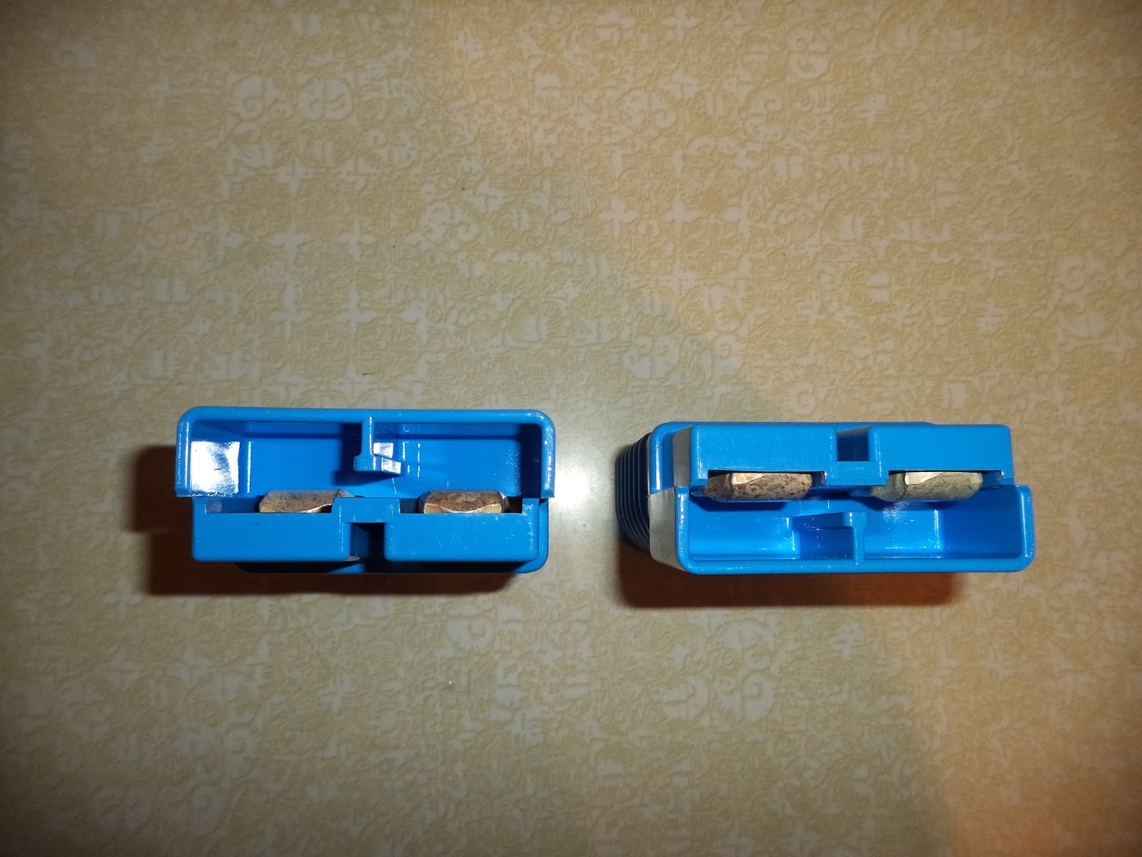
Picture DSC0694 showing the Total Source SY6321G1 Connector Kit Blue SB350 2/0 Awg 2/0 high power disconnect plug. (Ebay at $20.00 each).  Two identical plugs mate as a pair.


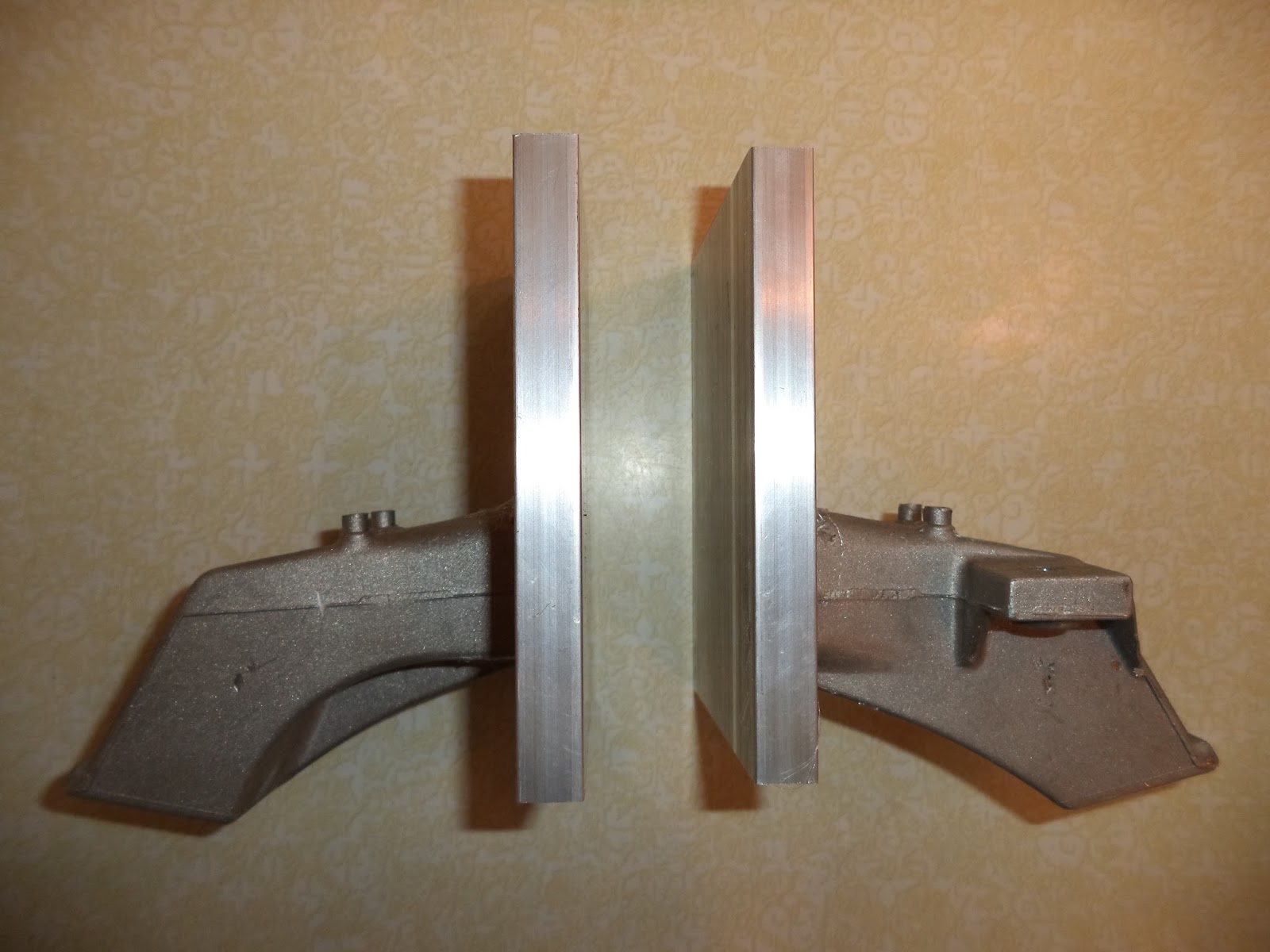
Picture DSC00733 end view of connector plugs.


Picture DSC00732 demonstrating how a pair of identical plugs mate together. 
 
The Total Source high power disconnect plug is manufactured for use in fork lift truck systems and it is not intended to be an active "switch", that is to say, it is not recommended to be disconnected during full current flow.  But, this nominally priced plug is rated at 350 amps continuous and it allows for total isolation of each battery pack during servicing.

A very convenient way to secure devices to the car frame is to use a Uni-Strut (also called Super-Strut B-1400-HS at Home Depot) style system in which bolts slide continuously within a steel track.  It is possible to bolt the track to the frame, and then adjust the location of the device without the need to re-drill the mounting surface.


Picture DSC00710 which demonstrates the 10-24 threaded square bolt (far left), Uni-Strut channel with two square spring bolts inserted, black plastic fuse base with twin (center) mounting holes, and the final fuse assembly bolted together.


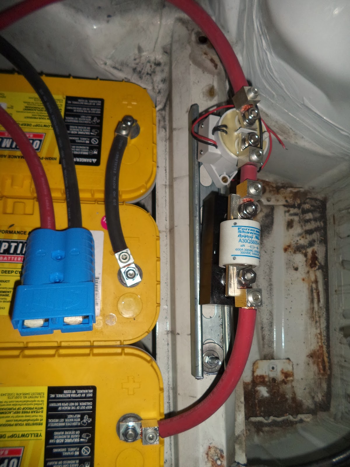
Picture DSC00709 showing a single 600 Amp Ferraz Shawmut A30QS600-4 fuse installed in series with a Kilovac Czonka III Relay during the preliminary installation when only the positive battery terminal was fused.


Picture DSC00716  showing the Uni-Strut style mounting base after securing the Czonka relay with a 10-24 bolt and 1/4" Nylon spacer and spring nut.
 
When installing the plastic mounting base for the Ferraz-Shawmut 600 amp fuses and the Czonka relays, it was noted that the plastic base could be bent if the bolt was tightened firmly.  Consequently, nylon unthreaded spacers were purchased from McMaster Carr (part # 94639A139, pack of 100 at $8.22) that were sized for #10 bolts and were 1/2" OD and 1/4" long.  When these spacers were inserted between the device and the mounting spring nut, the bolts could then be tightened without distorting the plastic


Picture DSC00713 showing the 0.35-0.63" gland nuts that were purchased for passage of the power cables through the aluminum bulkhead. 
 
The OD of the rubber insulation of the 2/0 battery cable was listed at 0.59 inch and it appeared to be compressible, so several gland nuts were tested that each could theoretically accommodate the wire.  A nut that was rated for wire that is in the range of 0.39-0.56" was found to be too small, and a nut that was rated for 0.51-0.71" was too large, but the ideal nut was one rated at 0.35-0.63" (McMaster Carr # 69915K56 at $4.43 each) and it held the cable very firmly. 


 Picture DSC00719 top view of the pair of 600 amp fuses and the pair of Czonka relays prior to mounting it adjacent to the rear battery pack. 
 
The blue plug in picture DSC00719 mates directly to a corresponding plug that connects to the 72 volt rear battery pack.  When the plugs are disconnected, the safety components (control relays and fuses) and the Soliton1 controller can be safely tested and serviced.  This module, with both sides of the battery pack fused and controlled, will replace the single fuse control previously shown in picture DSC00709 above.  A protective shield will be mounted around the relays and fuses to prevent accidental contact with the pack voltage.  


Picture DSC00721 end on view which shows the terminal strip connections for two pairs of Czonka relays. The second pair (left side) of low voltage Czonka relay control lines are hidden behind the red power cable.


Picture DSC00729 showing placement of the fuse module with twin fuses and starting relays.  Both the positive and the negative terminals of the rear pack can now be protected.


Picture DSC00728 top view of fuse module in place.  The pair of outputs (bottom right) are initially terminal blocks for testing, but they will be replaced with splice free cable lengths that will run to the second battery pack and Soliton1 controller located under the hood adjacent to the Warp11 motor.

Thursday, November 21, 2013

Optima AGM D31T Trial Fitting - Part 1

One of the goals of this conversion (if one puts aside the goal of the EVGrin) is to use this car as a test platform for different configurations and components.  This particular 1992 BMW 325i was chosen in part due to its availability, but also, it represents a much more significant choice in that the drive train appears in many BMW models and 10+ different years of BMW construction.  Thus, all of the efforts with this build should transfer very smoothly to later versions of this car, including even the BMW Z3 "rocket ship". 

Each iteration of this build is being tested  both for facility of fabrication and eventually for overall efficiency in turns of physical effort and expended ducats.  One of the background initial goals also includes the desire to see how many of the original operational BMW parts can be utilized within the build itself. 

The final test of the build will be in the application of the EV for a daily 70 mile work commute.  To achieve this final test point will demand the use of about 45 CALB-180 batteries in the final battery pack.   For initial trial work a total of eight Optima Yellow Top –8050-160-FFP-D31T batteries were purchased from Amazon.com.  These cells are rated at 75 amp hour capacity, and by comparison to other EV Album projects, this 7.2 kilo watt pack should allow for about 18 miles of range and should be sufficient to test out each of the various systems.  Additionally, if Murphy’s law presents itself, then the destruction of this AGM battery pack will not be nearly as painful as the destruction of lithium iron phosphates.
 
Battery Specifications:
 
YellowTop; Deep Cycle Battery; Grp. D31T;Cold Crank Amps 900;Crank Amps 1125;Res. Cap. 155;Ampere Hour 75;Threaded Terminal;L-12 13/16 in.;W-6.5 in.;H-9 3/8 in.  The T indicates a stainless steel threaded post.  59.8 pounds per battery.  Terminal configuration:  3/8"-16 UNVC-2A stainless Steel stud. 

(Note added 3/3/2016)

The studs have about 5/8" of exposed threads and they are fully threaded right down to the metal terminal surface.  But, the terminal surface is actually elevated slightly above the plastic battery case.  Consequently the absolute overall height from the plastic case to the top edge of the studs is really about 13/16".

Full data sheets can be found at:
 
 
With that said, a similar build (1995 BMW 325) that also utilized Optima Yellow Top batteries is that of Robert Nicol  ( http://www.evalbum.com/2896 ) .  He used a total of 12 batteries, and he placed six of the cells very nicely in the car trunk, above the plane of the wheel well.  He located the remaining six cells under the hood.  Examination of the 1992 BMW 325i wheel well, suggested that with a little modification, it might be possible to actually recess six cells within the wheel well itself.  This has been confirmed and will be described below.
 
 
Picture DSC00664 showing the initial placement of the Optima D31T batteries prior to wheel well modification.
 
The initial trial fit of the Optima batteries can be seen in picture DSC00664, and it was apparent that the center spare tire mounting bolt (visible in picture DSC0665 below) would need to be removed, and that the curved surfaces at the left side of the wheel well would also need to modified.


Picture DSC00665 showing the spare tire hardware mounting bolt prior to its removal.  This mounting bolt in part prevented the full six batteries from fitting symmetrically within the wheel well.


Picture DSC00669 demonstrating the space provided after the removal of the spare tire mounting bolt.  A sheet metal disk will later be welded to seal off this opening.
 
The removal of the mounting bolt and all sheet metal modifications described in this post were performed with a Craftsman 4.5 inch sander/grinder using a 1/16" (1.6 mm) metal cut-off blade(Picture DSC00686)
 
 
Picture DSC00686 of the sander/grinder that was used for the metal modifications.


Picture DFSC00672 with the proposed initial cut lines marked on the metal surfaces. This area is towards the front of the trunk.


Picture DSCF00673 after removal of the top triangular sheet metal portion, and after the completion of the vertical releasing cut, and after the curved cut was made at the base of the wheel well. (seen at the top of the picture).


 Picture DSC00675 showing a vice grip holding the partially bent curved surface adjacent to part of the straight bottom cut.  There are no releasing cuts and thus the curved section will not bend properly to lie flat against the bottom surface edge.
 
It was important when bending the sheet metal to provide releasing cuts at various points in the metal.  Without them, the metal buckled and it would not bend smoothly and it could not lay flat against the adjacent cut  surface.
 
 
Picture DSC00678-B after initial removal of the triangular wedge top portion and making the releasing cuts (vertical cut at the left and bottom horizontal cut).  This picture is the area at the rear of the trunk adjacent to the bumper.


 Picture DSC00679 showing the approximation of the metal surfaces.  A gloved hand is holding the bottom of the sheet metal for demonstration.  The three releasing cuts (two in the center area and one at the far right)  were required to allow the initially curved metal surface to bend back upon itself. 
 
 
Picture DSC00683 showing the successful initial placement of the six Optima Yellow Top batteries in the wheel well.  The red terminal at the upper right and the black terminal at the upper left would be the outputs. 
 
 
Picture DSC00684  showing the available space created after the wheel well modifications and prior to final welding.  Note that the center sheet metal portion remained intact and is structurally sound.
 
The last picture (DSC00684) also shows the difficulties presented in attempting to MIG weld the sheet metal.  Previous welding of  0.125 and 0.25 inch thick steel plate when fabricating the motor mounts (described in previous posts), although perhaps not very pretty, was rapidly learned and successful.  It was found to be much more difficult to weld the sheet metal (measured to be only 0.036 inch thick).  The electric arc blasted holes very easily and rapidly through the sheet metal, and the proper amperage and welding wire feed rate has not yet been worked out.  The bolt and washers visible to the right of the brown welding attempt, was used to hold the two sheet metal edges adjacent to each other and in the same plane.  It may turn out that oxy-acetylene stick welding will prove more successful in this welding effort.  More on that later.
 
The hope will be to add additional sheet metal patches to fill in the current openings and upon completion have welded joints that are both structurally sound and water tight.  Since the batteries are recessed in this design attempt, it may be possible to later reinstall the original trunk floor carpeting and thus create a pleasing finished interior appearance.


Tuesday, November 5, 2013

Power Electronics 2 - Dual Xantrex XFR20-130

A second Xantrex XFR-20-130 power supply was purchased from Tim at Industrial Equipment Finder  (telephone 866-293-8981).  The power supply that he shipped works beautifully and was very clean.  Each Xantrex XFR20-130 is rated at up to 20 volts and up to 130 amps, but if the outputs of the two units are put in series, then the pair of power supplies will then deliver 40 volts and 130 amps (5.2 Kilowatts).  Since 1 HP equals 0.746 kilowatts, this represents about 6.97 HP.  This is certainly enough power to test the air conditioning or gear shifting, and possibly to get into some trouble !!

 
Picture DSC00654 showing that when the outputs are put in series, and each power supply is set at about 20.5 volts (no load), then the combined output is about 41 volts.
 
 
 Picture DSC00655 showing that when one power supply is set at about 20.5 volts, the second power supply is set at about 0 volts, and the throttle is activated, the amperage produced from one power supply then passes through both power supplies.

When both power supplies were set at 15 volts (30 volts total), the draw was about 35-40 amps.  At these settings the motor's rpm increased to 1800-2400.  The rpm sensor will next need to be fine tuned so that it will provide a steady measurement. Important To Note, all these tests were conducted with the transmission in gear, and with the rear wheels fully rotating, to provide an active load.  If the Warp 11 were not under load, it is presumed that at these higher voltages the motor rpm's would quickly red line and beyond, with damage to the Warp 11 soon to follow.

Tuesday, October 22, 2013

Power Electronics - Soliton1 and Xantrex XFR20-130


Two main projects (power electronics and battery pack) remain before achieving the first drive and EV grin.   The power control electronics effort began with the purchase of a Soliton1 controller from www.EVBimmer.com .  The Soliton1 is a 300 KW (400 HP) brushed DC motor controller that can operate with a battery voltage range of 9 to 340 volts DC.  The Soliton1 output can provide 1000 amps of maximum current. 


Picture DSC00530 showing the Soliton1 power controller.  This unit came with software version 1.053

To allow testing of the Warp 11 and the Soliton1 without a battery pack, a Xantrex XFR20-130 DC power supply was purchased from Ebay (picture below).  This unit can provide regulated voltages between 0-20 volts and continuous current up to 130 amps. 

Used together, the Soliton1 and the Xantrex will allow both bench top testing of the Soliton1 and direct operational testing of the Warp 11 and the BMW 325i drive train (including 5 speed shift testing).  There will be no danger of draining a battery pack while the Xantrex is in use  !!!
 

Picture of Xantrex XFR20-130 DC power supply which will provide a regulated 0 to 20 volts and a regulated 0-130 amps. 

The Xantrex power supply requires 240 volt AC input, so a power cord with a male plug adapter was assembled with parts from Home Depot.  The new power cord now allows the unit to be plugged into a custom 50 foot 10 AWG extension cord whose opposite end plugs directly into the clothes dryer outlet in the basement.  It is intended in the future to install a 240 volt wall outlet conveniently in the garage for use with a car charger when needed. 

A Throttle Position Sensor (TPS) was purchased from EVNetics  (picture DSC00593) and it was connected to the Soliton1 followed by software calibration (100% and 0% throttle positions) using a lap top computer.  When the TPS was later set at its minimum, the Xantrex was drawing at idle 0.72 amps (246 volts and 177 watts, P=EI) and it was providing to the Soliton1 zero volts and zero amps..  When the TPS was at 100% (maximum), the Xantrex was drawing initially 9.2 amps (246 volts and 2263 watts), but as the Warp 11 came up to speed, the input amperage dropped slightly to 9.06 amps (246 volts and 2229 watts).  At the same time, at 100% throttle, the Xantrex was providing to the Soliton1 initially 19 volts and 101 amps (1919 watts), but as the Warp 11 came up to speed, the Xantrex then provided 19 volts at 85.2 amps (1618 watts). 


Picture DSC00593 of the EVNetics throttle body showing the standard auto type three wire plug and socket.

An RPM sensor was also obtained from EVNetics for testing and it was temporarily installed on the accessories end of the 0.875 inch Warp 11 shaft (picture  DSC00592).  This sensor allows the Soliton1 to collect RPM data which can then be output on the lap top computer display.  At full throttle the Soliton1 indicated a maximum rpm of between 850 and 1150, but the data collection was not stable and further study will be necessary to learn what is causing the rpm bounce during the measurement.  It is intended to later use the 58 tooth OEM BMW harmonic damper for measurement of the motor rpms.  The harmonic damper signal can be sent directly to the dashboard instrument cluster to allow real time driver observation, but some electronics interface will be needed to allow the Soliton1 to understand the 58 pulses on/2 pulses off signal that the harmonic damper produces.


Picture DSC00592 of the 0.875" ID Aluminum exciter ring with four steel set screws as installed on the Warp 11 shaft.

The Soliton1 requires a 12 volt power supply that must be capable of providing up to 8 amps for the engagement of the contactors on start up.  During subsequent continuous operation only about 1 amp is then required.  A search on Ebay under "regulated transformer power supply for LED" provided several inexpensive choices and one that provides 12 volts DC/10 amps and cost $15 was selected.  This power supply will also be used to provide the 12 volt power required by the JLD404 Intelligent AH Meter.  After testing is complete, the BMW 325i accessories 12 volt lead acid battery will supply all the required 12 volt energy.


Picture DSC00599 showing the 12 volt/10 amp DC output power supply (120 AC input).

Shelves have now been added to the previously existing pallet racking that is adjacent to the 325i in the garage.  This work area will provide space for additional meters and oscilloscope as well as easy access to the Warp 11 and the BMW 325i's electrical components during testing.


Picture DSC00598 showing the two shelves of work space that was created on the pallet racks adjacent to the 325i.


After the future purchase of an electric power steering pump, the battery pack is expected to be the final major component investment. 

Sunday, September 22, 2013

Motor Mount - Welded Steel 2.0

While developing new welding skills this week, work was continued on the new design for a steel mounting clamp for the Warp 11.  Each effort demonstrated new challenges for work set up and metal preparation.  In the future, all of the surfaces that will be welded will be light sanded to remove mill scale before the pieces are tack welded together for assembly.  It is much harder to remove the scale after the pieces have been partially assembled.  Another significant detail, learned by trial an error, is the need to use multiple vice grips to hold the assembly in the correct planes and orientation prior to tack welding.

 
Picture DSC00491 showing the beveled edges of the center steel prior to tack welding the angle iron pieces to each side.


                          Picture DSC00497 which demonstrates the setup prior to welding. 

The initial half of the curved steel clamp was carefully measured, the angle iron "flanges" positioned with vice grips, the pieces tack welded together, and finally all of the seams completely welded and ground down for a smoother surface finish.  Welding of the complimentary steel clamp required more care to ensure that both sets of flanges were both in alignment with each other and in the same plane.  Picture DSC00497 above demonstrates the method used.  Initially the work was placed in the bench vice to hold both (right side of the picture) angle iron pieces firmly and in parallel alignment.  An aluminum flat stock was then vice gripped to the outer face of the previously welded angle iron (on the left side), and finally the remaining angle iron (front left) was held (top to bottom) with another vice grip after it was positioned flush with the aluminum plate.  Tack welding locked in the required position, and then complete seam welding finished the job.

 
Picture DSC0495 with Peter from Boy Scouts Troop 95 demonstrating the proper method for welding the steel angle iron.
 
 
Picture DSC00505 showing the side view of the original aluminum top design with the steel bottom support ring.  Note that this design will allow for the bottom extraction of the Warp 11 motor without removal of the upper aluminum clam shell and the side mounting adapters.  This capability may be of value if the space above the aluminum clam shell is occupied by a controller or with batteries that may be difficult to remove and replace.


Picture DSC00508 shows an oblique view of the mounting flanges prior to welding the BMW OEM sectioned piece to the outer aluminum flange.  Two plastic spring clamps were used to hold each of  the aluminum pieces together for the photograph.


Picture DSC00512 showing one of the new steel rings with the welded angle iron. This configuration could be used when the engine mounts are higher than the equator of the rings. 


Picture DSC00514 showing one of the new steel rings with the welded angle iron. This configuration could be used when the engine mounts are lower than the equator of the rings. 


Picture DSC00502 with both steel rings in place.  Prior to attaching rubber gaskets onto each inner curved surface, any excess welding buildup will be ground smooth.  The camera angle does not show it properly, but both left and right mounting faces are actually parallel to each other and both are perpendicular to the floor. 
 
 
Picture DSC00504 showing an oblique view of the mounting faces of the combined top and bottom steel rings.  The required location for the mounting bolt holes will be determined after the assembly is trial fitted into the motor compartment. 


Monday, September 2, 2013

Motor Mount - Welded Steel 1.0

An attempt was made to weld one of the sectioned OEM BMW motor mounts after it had been hot glued to the aluminum mounting flange, but the hot melt glue did not hold the correct orientation of the two parts during transport and then welding.  The parts were then separated with an abrasive cutting disk and the new plan is to reaffix the parts with hot glue followed by withdrawal of the pieces from the car and tack welding them prior to transport.  The tack welded parts should be safe for transport and the orientation would not be lost due to softening of the glue during the welding process.

To develop the skill required to tack weld aluminum (which requires 100% Argon welding gas), it was elected to practice steel MIG welding using an available Miller Matic 140 Autoset.  Previously only flux core welding had been attempted, and the amount of time required to clean up the resulting flux residues was disappointing.  This was especially true when the weld was incomplete or had to be redone.  A reality too often to confess.  This time it was elected to spring for the rental of a tank of  Argon/Carbon dioxide (75%/25%) welding gas.  Best decision ever for an amateur welder!  The clean up using a wire brush was extremely simple and the repair of defects very fast.

A previous all steel alternate motor mounting design was used as a practice project.  This design could be exchanged for the previously described clam shell style aluminum foundry top casting.  After welding flanges to this top ring, the bottom support ring attached with bolts.  Holes would then be drilled into the top steel flange to allow the OEM BMW support (described in the last blog posting) to be bolted to the flange surface.


Picture DSC00437 showing the 2" tall 2" x 3"angle iron prior to being welded to the steel support ring. 


Picture DSC00436 showing an oblique view of  the angle iron pieces prior to being welded to the steel support ring. 


Picture DSC00435 showing vise grips securing the three steel pieces prior to tack welding.  By leaving the excess steel toward the center of the support ring, the vise grips had a secure surface to hold to.


Picture DSC00438 showing the welded mounting surfaces attached to the support ring after the excess steel had been removed from the internal curved surfaces.


Picture DSC00440 showing the side view of  the welded mounting surfaces attached to the support ring after the excess steel had been removed from the internal curved surfaces.


Saturday, August 17, 2013

Motor Mount 3.5

The initial trial fitting revealed that the 3.75" tall x 4.0" wide flange required more mounting surface at the bottom edge.  New flanges measuring 5.0" tall and 4.0" wide were then fabricated, trial fitted, and hot glued together.


Picture DSC00371 showing the side (viewed from the front of the car) of the new taller flanges fitted to the sectioned BMW OEM parts.


Picture DSC00372 of the passenger side (left) and driver side (right) after being hot glued together.
 
 
It was then desired to weld the sectioned engine mount directly to the flanges.  Although the flanges were known to be alloy 6061, the BMW OEM parts were of unknown composition, and it was unknown whether the two metals would be compatible to welding.  To determine the alloy type of the sectioned engine mount, it was tested with a Glow Discharge Atomic Emission Spectrometer.  The test sample surface was first sanded and then placed within the vacuum chamber of the instrument.  After ablating the surface with a laser, the spectral analysis indicated the approximate (100.19%) composition to be:

Aluminum 81.9%
Silicon 12.40%
Copper 2.99%
Zinc 1.78%
Iron 0.78%
Manganese: 0.20%
Tin 0.14%
 
This data is consistent with an aluminum die casting alloy similar to alloy 380 or 384.  A professional welder was then able to test weld the two parts together using a TIG welding apparatus.  Unfortunately, the hot glue was not strong enough to hold the pieces during the welding process and the precise orientation of the flange to the sectioned piece was lost .  The next attempt will again use the hot glue for proper initial orientation and removal of the two pieces from the car, but, it will then be attempted to spot weld the two pieces with a MIG welder prior to taking the parts back to the professional for final circumferential welding.  


Picture DSC00373 showing the circular impact point left on the sample section of the BMW OEM part after the laser ablated the metal. 


Picture DSC00 showing the first try at welding the BMW OEM part to the flange just prior to drilling the mounting bolt holes.