Thursday, June 26, 2014

Routing the Rear Battery Cables to the Motor Compartment 1.0


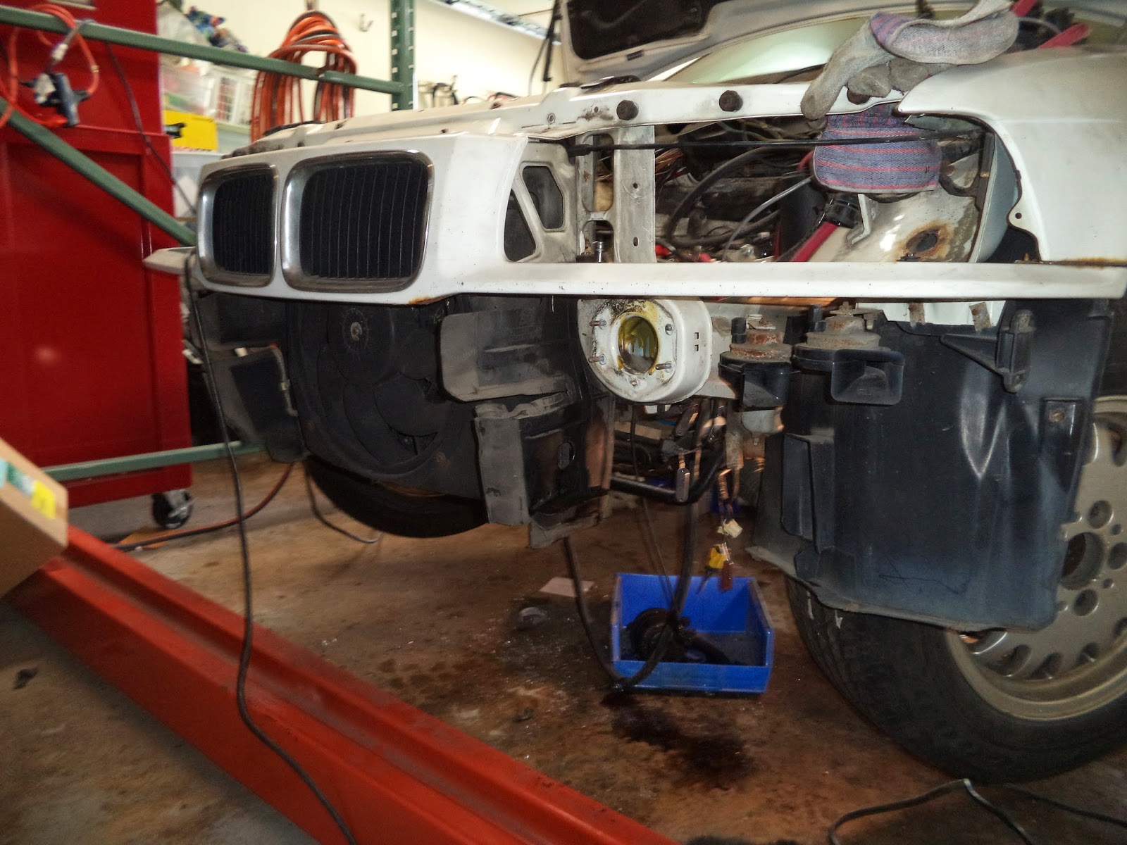
Considerable mental energy has been expended regarding the problem of connecting the rear battery pack to the front battery pack.  Several goals are desired: (1) protecting the rubber insulation of the cables from mechanical damage;  (2) isolating the voltages from water (rain or standing water in the roadway); (3) physical placement of the cables as close together as possible to minimize the creation of magnetic fields; and (4) placement of the cables within a shielded conduit, or channel, or metal braid, or copper tape, to minimize the radiated electric fields.

Examination of the underside of the car suggested a pathway adjacent to the power brake lines on the left side of the car.  This area is very slightly recessed into the base of the car.  The outer diameter of the rubber insulation of the battery cables is about 1.5 cm.  The rubber would protrude below the base of the car and it would be vulnerable to potential damage from road debris.  If the cables coursed through in an Aluminum or Steel channel for protection,  then the pathway would still be the lowest point of the undercarriage, and water would tend to collect within the structure.  Placing regular openings in the channel to allow drainage, then exposes the rubber to potential damage.  The placement of each cable in separate metal conduits suggests an advantage since the conduits could be custom bent to rise up into the motor and the trunk compartments.  The addition of bulkhead fittings could make the system relatively water tight.  Unfortunately, placing each cable in separate metal conduits may induce a current in the conduit in the space between the two wires and this could result in the heating of the conduits.  The field forces on the wires may also cause movement of the cables within the conduits and eventual chaffing of the insulation over time.  With these observations in mind it was elected to study how BMW routes the OEM battery cable from the trunk to the motor compartment.


DSC01288 showing the view looking forward of the OEM battery cable as it disappears into the front right bulkhead wall of the trunk.  The cable passes through a black rubber gasket which is seated in the punched out metal wall.


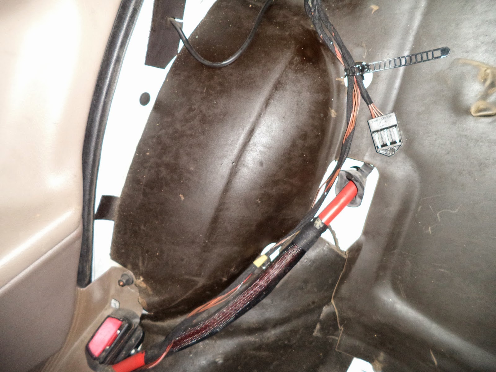
DSC01289 after removal of the back seat this view shows the battery cable as it enters the cabin to the right of the right rear wheel well and descends downward toward the seat belt clip.  There is a 10 inch plastic woven sleeve over part of the cable.  The process for removal of the rear seat elements will be posted later.


DSC01290 showing the battery cable entering under a tan colored plastic trim by the side of the seat and the base of the door.  The black plastic nut adjacent to the seat belt clip (right) was next removed.


DSC01311 showing the chassis hardware after its removal from the frame (hole in center of picture)  using a pair of pliers.  This hardware also serves to lock the floor carpet into place.  The plastic trim piece must be moved sideways to disengage it from the chassis hardware.  Picture DSC01330 shows the underside of the plastic trim piece and the slot that engages the chassis hardware.


DSC01330 showing the shape of the sliding portion of the underside of the plastic trim.  There are (or were) two of these on this trim piece.


DSC01296 after removal of the plastic trim guard.  This trim piece is removed by sliding the plastic trim piece backwards and sideways.  See picture DSC01311 and DSC01330 for details. 


DSC01314 showing the descent of the battery cable into a tunnel created by black protective plastic trim elements.  Since it is intended to replace the stained carpet during the EV conversion, a shop knife was used to excise the flooring carpet that obscured the path of the battery wires.  This view is from the front looking back at the passenger seat.  The large round opening at the center right was previously the access point to the ICE fuel tank and fuel pump.


DSC01315 showing the route taken by the battery OEM cable. View is from the back seat looking forward to the front of the car.  The structure to the top left is a ventilation duct that originates from under the carpet that covers the center console.  All of the black components were hidden under the carpet, and due to a layer of rubber foam that was bonded to the underside of the carpet, there was never any previous awareness that these utilities were hidden in this way.


DSC01328 after the plastic "tunnel" pieces were removed all that remained was the ventilation ducting.


Picture DSC01320 demonstrating the trim tool that was used to carefully pry out the plastic retainer that secured the ventilation duct to the floor.  The stud at the top left previously held the front left frame of the passenger seat.


Picture DSC01331 of the pathway under the cross brace.  It is hoped that there is sufficient room adjacent to the OEM battery cable to route two additional battery cables through the frame.


Monday, June 9, 2014

BMW Wheel Dome Body Work Repair 1

Since the radiator/bumper/grill had been removed it was very easy to gain access to the motor compartment.  It was elected to make the sheet metal body work repairs within the motor compartment prior to installation of electrical components.  Penetrating rust was present on both wheel well domes around sheet metal screws in what initially appeared to be relatively small areas.   As is stated repeatedly in the literature, once observed "paint bubbles" are opened up, significant lateral rust damage can frequently be discovered.  That was the case in this repair.


Picture DSC01145 showing the right side rust on the wheel well dome prior to debridement.


Picture DSC01177 showing the intermediate stage of rust removal of the rust that was discovered under the "paint bubbles"


Picture DSC01247 showing the final prepared area ready for grafting.  The borders were made as straight as possible to facilitate the placement of the metal graft.


Picture DSC01213 showing the salvage yard donor 525iA BMW from which sheet metal was cut using a thin abrasive metal cutting wheel.  Since the donor location had a similar curvature as the destination location, it was expected that very little bending would be required for the graft.


Picture DSC01226 of the donor sheet metal.  The piece was placed behind the opening where the rust had been removed and the outline was traced with a pencil.  On the workbench an additional margin was added and the sheet metal trimmed with a cutoff wheel at the outer margin.  Paint was then removed with a wire wheel to yield the graft shown in picture DSC01232.


Picture DSC01232 showing the sheet metal graft prior to crimping a step margin into the metal.


Picture DSC01224 of an IR 114GQC Air Hammer connected to an S & G Tools pneumatic crimper attachment.


Picture DSC01225 showing a close up of the die portion of the crimper tool that will produce a step on the margin of the sheet metal graft.


Picture DSC01236 demonstrating the outline formed after the crimper tool was used to produce the step in the sheet metal graft.  About 2 minutes was required to produce the step, and then about 5 minutes was required to touch up the edges with a piece of metal bar stock and a hammer.


Picture DSC01237 demonstrating the insertion of the sheet metal graft into the prepared defect in the BMW wheel well dome area.  The graft will next be tack welded into place followed by welding of the entire circumference of the graft.


Saturday, June 7, 2014

Removal of the SRS (Supplimental Restraint System) sensors.

Part of the process of preparing the wheel dome area for welding required the removal of all electrical wiring and plastic components.  Removal of the right side SRS crash sensor, located above where the washer reservoir was previously positioned, was necessary to prevent heat damage from the welding process. 


Picture DSC01220 of the right side SRS (Supplemental Restraint System) crash sensor.  This sensor is a part of the air bag safety feature of the E36.  These sensors complete a circuit if the impact is a frontal collision within 30 degrees of the center line and the vehicle is travelling above 12 mph.  If these conditions are met, then the air bag will deploy.  If the system is working properly, the SRS light will illuminate for 6 seconds on start up and then go out.  Lack of illumination, or flashing for 5 minutes after the initial 6 seconds, or failure to light, are all indications that the system is defective and needs dealer servicing.

The screws that secure the sensor to the mounting bracket on the wheel well are unusual.  My friend and automobile expert Peter saved the day as in his tool bin he had a set of Silver Eagle tamper resistant Torx  socket set.  The socket that fit perfectly was labeled T30H, and this is a T30 Torx with a H (hole) in the center.  McMaster Carr sells a low cost version as a fold up Torx-key set (catalog number 55515A22 at $15.39).


Picture DSC01219 showing the Silver Eagle T30H tamper resistant Torx socket (left) and one of the removed screws (right) after removal of the right side SRS crash sensor.  It is believed that the sensor will not be damaged as long as the 12 volt power is turned off.  If power is applied and the sensor is dropped, then Chilton indicates that the sensor will need to be replaced and dealer servicing required to reset the resultant error codes.

Sunday, June 1, 2014

325i Front End Disassembly


There is a need to repair some perforating rust in each of the front wheel wells.  To weld these areas requires that all plastic and adjacent wiring be removed to prevent collateral damage.  To make a careful repair will require easy access to each area, thus, it was finally decided to remove the front end of the car.  This is something that should have been done from the very beginning as it would have allowed both easy and ready access to all of the areas of the motor compartment.  The time spent for the removal of the front end (9 hours for a first time effort) would easily have been recovered by the time saved during many of the previous process steps and component fittings.


Picture DSC01092 showing the rust damage on the left side wheel well (engine compartment view).


Picture DSC01078 showing the right side rust damage adjacent to the windshield washer fluid reservoir (right wheel well view).  The plastic liners for both wheel wells were also removed during the disassembly process.


Picture DSC01060 showing a different (top) view of the rust damage located adjacent and below the windshield washer fluid reservoir.  The square outline was caused by a rubber cushion that was attached to the bottom of the plastic washer fluid reservoir.


Picture DSC01075 showing the tagged wires that were initially connected to the right side headlight cluster.  As each wire was removed, a tag was attached with a paperclip, and a picture taken showing the connection point and the tag.  In the shop a digital camera is an essential part of the build process.  Previously there were problems with lost paper tags that either tore off or became illegible from dirt or fluids.  All of the wires originate at the left (driver) side in the fuse box area and they route forward to the left headlamps, then across the grill to the right headlamps, and finally they continue backward to the washer fluid reservoir.  The entire "snake" of wires was collected and placed on top of the fuse box to get it away from the work zones.


Picture DSC01113 showing the front end after removal of the bumper (picture DSC01112).


Picture DSC01112 of the separated front bumper.


Picture DSC01109 showing the hood latch (bottom) and the removal of one of two long screws that attach the AC condenser to the top of the grill housing.


Picture DSC01127 showing the AC condenser after its removal.  The engine condenser had previously been removed.


Picture DSC01108 showing the removal of 3 x T30 torx screws.  The hood latch could not be separated from the grill housing until  2 additional screws were removed to separate the front grill housing from the rear grill housing (picture DSC01138).


Picture DSC01138 showing that the front grill assembly (top) was partially separated from the rear grill housing (bottom) after the removal of 2 x 10 mm screws.  The rusted block in the center is the left side (driver) hood release.  The wire the exits to the top right terminates at the hood release lever within the cabin.  The wire exiting to the lower left is connected to the right side hood release.   Both either need to be rebuilt or replaced.


Picture DSC01139 showing the grill housing separated from the front of the BMW.  The four holes in the lower round areas attach to welded studs attached to the frame (as seen in picture DSC01154 and DSC01155).


Picture DSC01154 showing the front view of the chassis after the complete removal of the bumper and the grill housing.


Picture DSC01155 showing the front on view of the motor compartment after the compete removal of the bumper and grill housing.  It is now possible to walk into the motor compartment and work on all of the mechanical systems without either reaching over the radiator and grill or climbing into the motor compartment and crouching between the motor and the radiator.  Much improved!!