The 245 k bytes two dimensional DXF file that was created and previously described in the 6/30/2023, blog post was used within a CNC program to create the 2D outline of the housing. That information was loaded and massaged in a program called Master Cam ( https://www.mastercam.com/ ) to yield a file that was then only 3706 k bytes. The third dimension included at this point to define the depth of the internal and external cuts and the overall thickness of the plate. Finally the Master Cam data was loaded into a G and M Code that the CNC directly understands.
https://en.wikipedia.org/wiki/G-code
edited 9/5/2023

DSC01928 showing one of the previous adapter plates (from a casting) overlaid on the 15.875"x13.625"x2" billet of 7075 Aluminum.

DSC02038 showing the trial "plate" produced from a piece of scrap 0.067" thick 6061 Aluminum using the DXF file after it was modified as described above to be compatible with the CNC machine. The transmission is shown standing on its drive shaft and the view is into the transmission housing. This trial plate confirmed that the outline and hole locations were all correct prior to cutting the expensive 2" thick billet.

DSC02039 showing a detail of how precisely the DFX file conforms to the actual outline of the transmission housing.

DSC02041 of the Leadwell V-40 CNC machine that was used to manufacture the billet plate.
These machines are available on eBay and other resale platforms for $27.5 - 40K. Some tooling is included. https://www.leadwellcnc.com/

IMG_9613 showing the billet loaded into the Leadwell CNC prior to machining. Edited 9/5/2023
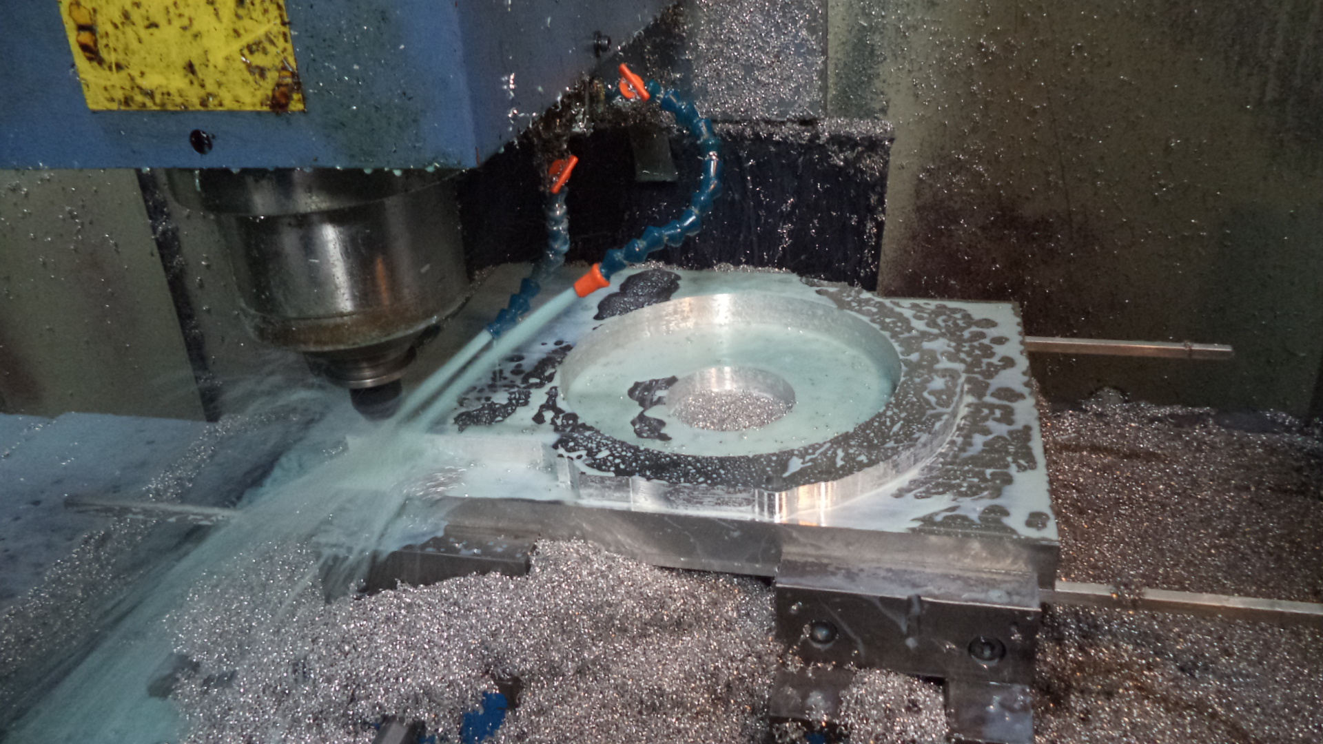
DSC02043 showing the initial cuts being made on what will be the transmission side of the future adapter plate.

DSC02073 Hyper9 (drive) side of the final billet adapter plate. The hole at the 12:00 is the center top and the hole at 6:00 is the center bottom of the transmission.

DSC02075 oblique view of the Hyper9 (drive) side of the final billet adapter plate.

DSC02072 Getrag transmission side of the final billet adapter plate.

DSC02076 oblique view of the Getrag transmission side of the final billet adapter plate.

DSC02080 compares the transmission side of the original adapter that was made as a casting (left) to the billet adapter (right). The casting weighs 4.92 kg and the billet weighs 5.66 kg. The original casting is several years old and it has air oxidized and discolored in the shop environment.

DSC02078 compares the Hyper9 (drive) side of the casting adapter (left) to the billet adapter (right). The casting adapter has more mounting holes to also accommodate either the Warp 9 or Warp 11 DC motors. The casting hole pattern did not position the top center position of the transmission and the top center position of the Hyper9, so the 8 hole pattern closest to the 4" center opening was rotated slightly to the left. The new billet hole pattern allows for the attachment of the Hyper9 mounting platform (DSC01563 of 2/23/2023 post) and the Hyper9 controller enclosure (DSC01830 of 5/20/2023 post) such that each are now level and parallel to the floor. The holes in the billet at 1:00 and 7:00 are the top center and bottom center of the transmission respectively.
updated 9/2/2023