An Orion BMS-48 Cell Kit controller was purchased ($1205) from EVolve Electric. This kit included:
Main Controller
Orion 48 (REV - E2)
Serial # L4574D00 ;
36 Cell Tap Harness;
12 Cell Tap harness;
I/O Harness;
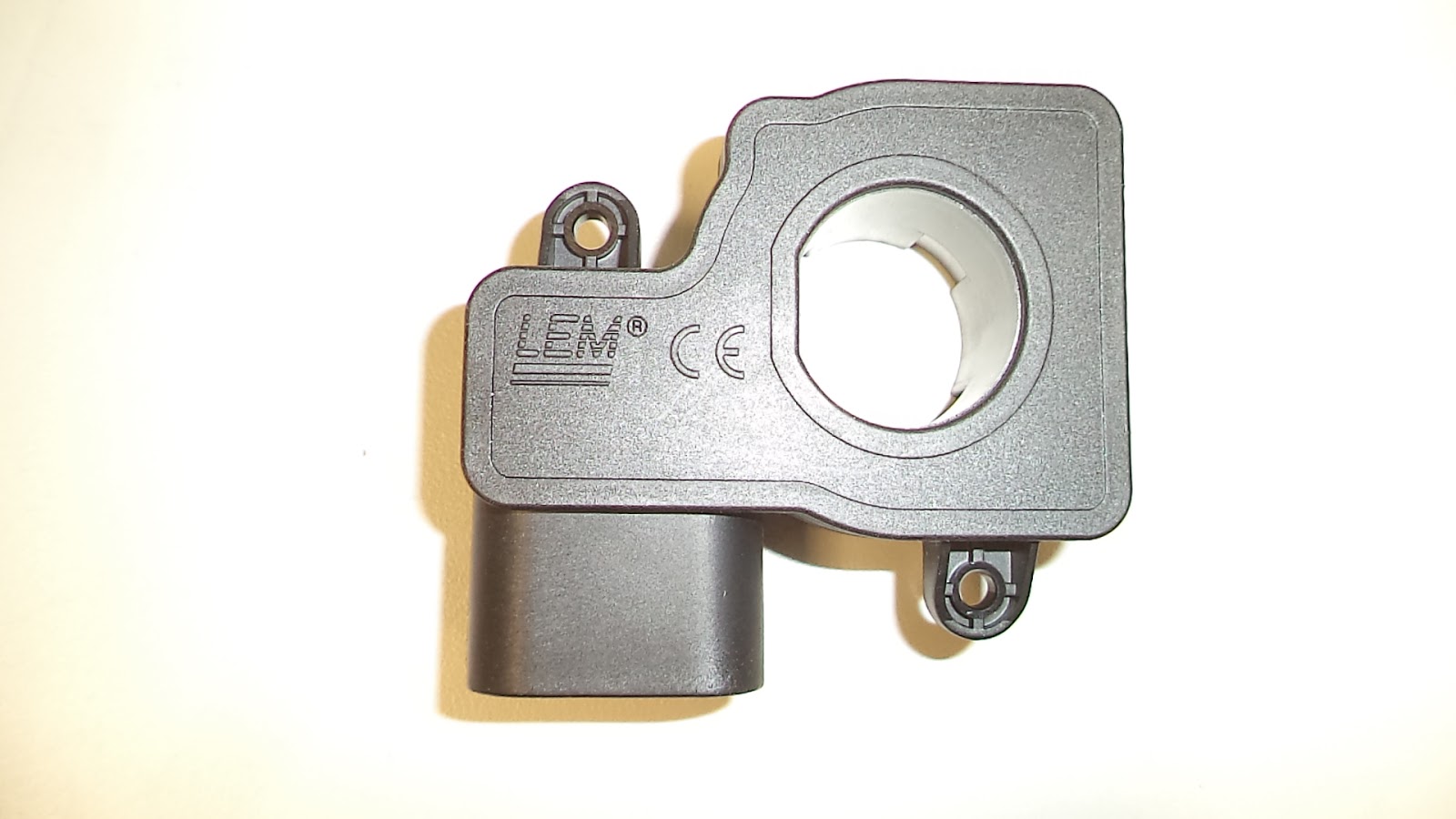
400 Amp Current sensor with (4) Pre-Wired Thermistors;
CAN adapter;
and a Utility Disk CD which contains the Orion BMS Utility
(also found here:
http://www.orionbms.com/manuals/utility/ );
Software Manual (also found here:
https://www.orionbms.com/features/pc-software/ );
and Wiring Manual (also found here:
http://www.orionbms.com/manuals/pdf/wiring.pdf ).
Since the Tesla batteries each have 2 thermistors and the six Tesla modules require a total of 12 sensors, an Orion Thermistor Expansion module was purchased ($207). This module interfaces with an additional 80 thermistors.
To facilitate wiring the Thermistors to the Orion BMS an 6' Orion Thermistor Wiring Harness was purchased ($52) which has 20 pre-populated thermistor taps.
DSC05617 oblique view of Orion BMS enclosure.
DSC05618 bottom view of BMS enclosure
DSC05614 side view of Orion BMS enclosure (2 connectors + Ethernet?). The Thermistor / Current Sensor socket on the far left connects to the white 16 pin plug labeled 371 and shown on the left side of picture DSC06316. The larger white socket on the right is labeled the Main I / O Connector and it mates to cable CWHMIO2-W1546D19 shown in picture DSC06322 below.
DSC05613 side view of Orion BMS enclosure. The far left socket is used for Cell Groups 1-3 and the middle socket is used for Cell Groups 4-6. The far right hand socket is not used.
DSC05600 of the Orion BMS Thermistor Expansion Module that permits xxx different Thermistors to be monitored.
DSC05601 of the Orion Thermistor Expansion module (three connector)
Cable labeled WHTHEXPO2-W156640 (picture DSC06315 shown below) connects to the far right socket.
DSC05602 of the Orion Thermistor Expansion module (two connector)
DSC05609 top view of 400 amp current sensor. As shown above, the power cable opening is 21.57 mm ID left to right, and 22.62 mm ID top to bottom.
DSC05608 of the current sensor showing the internal pins labeled D, C, B , and A. This current sensor mates to the purple cable socket (part number CWHCURTH-W1559453) shown below in picture DSC06316.
The current sensor has the following markings:
LEM
716183093257
>PA66-GF25<
Wiring harnesses that were included in the Orion BMS-48 Controller.
DSC05619 of the multiple wiring harnesses provided.
The part numbers as printed on the exterior of the plastic bags were sometimes different than the part numbers located internally so both numbers are listed.
(starting at 12:00 - top center ):
CWH126-W1472408, with internal part number CWH126 KSM1915
DSC06308
DSC06307
This cable has 12 orange wires labelled 1 to 12 and 1 black wire labeled 1. Plastic plug is labelled 369.
WHTHEXPO2-W156640, with internal part number of CWHTHEXP02 KSM5216.
DSC06315
DSC06314
7 wires, with bottom row (as shown):
blue, black, purple, yellow and black.
top row with red, followed by 3 empty plug locations, and finally a red wire. The first black wire is paired with the first red wire in the lower row. The plastic plug is labelled 420. This cable connects to the Orion BMS Thermistor Expansion Module in the far right socket shown in picture DSC05601.
CWHTP-W1574C00, this cable had an internal part number of CWHTP KSM0817
DSC06304
DSC06305
A pair of wires, orange and brown. Black cable covering. 8 wire plug using only 2 wires, orange and brown. The plastic plug is labeled 384.
CWHMIO2-W1546D19 (bottom right of picture DSC05619) had an internal part number of CWHMI02 KSM4716. The cable package also included 3 x 120 ohm resistors (DSC06334).
DSC06322
DSC06321
Appeared to be 18 wires, but the 2 black wires ( 1 short and 1 long) were actually 3 wires each, both sets covered in black sleeves. The plastic plug is also labeled 371 and it connects to the right side socket shown in picture DSC05614 above.
DSC06334 of what appears to be 120 ohm resistors.
CWH366-W155550F with an internal part number of CWH366 KSM5116.
DSC06313
DSC06312
A black wire followed by 12 orange wires (labeled 1 to 12), then a black wire followed 12 red wires (labeled 13 to 24) , then a black wire followed by 12 yellow wires (labeled 25 to 36), and finally a black wire. The black wires are labeled 1, 13, and 25. The plastic plug is labeled 420.
CWHCURTH-W1559453, this part had an internal part number of CWHCURTH-D KSM5016.
DSC06316
This cable has a white plug, a purple plug, and 4 pairs of black wires. On the side of the purple plug (which has an external black housing and 4 wires connected to it) is indicated: DELPHI 11 PBT-GF20. This purple plug attaches to the current sensor shown in picture DSC05608 and 5609 above. When the purple plug is viewed as in picture DSC06316 above, the far right is pin A and the far left is pin D.
The white plug has 12 wires (4 go to the purple plug) and the white plug is labeled 371.
THERM2002-W1573D0B, which appears to have 20 thermocouples with 2 wires each.
CWHTHEX202-W1531B? (center of picture), this part had an internal part number of HTHEX202 KSM4116.
DSC06320
DSC06319
DSC06318
top row: black followed by 5 white, then black followed by 5 white.
lower row, identical to upper row. The plug is labeled 371
DSC05620 of the CANDAPTER CAN bus interface with software