Wednesday, August 12, 2015

Installation of a Shunt for the JLD404 Intelligent AH Meter


There are several devices available that can provide information about the number of amps being provided (or received by) the battery pack during the operation of the EV.  These programmable devices include but are not limited to the following:

LEM CAB300-C Flux Gate Current Sensor
ZEVA Fuel Gauge Driver
JLD-404 Intelligent Amp Hour Meter
Xantrex LinkPro Battery Monitor
Electric Vehicle Interface Controller (EVIC)

The LEM CAB300-C and the ZEVA Fuel Gauge Drive do not require direct connection to the drive battery pack while instead they require that one of the power cables pass thru a coil that is integral to the sensor.
                                         LEM CAB300-C Flux Gate Current Sensor

Picture of LEM CAN bus current sensor (  http://www.lem.com/hq/en/content/view/543/126/  )  One of the cables from the drive battery pack  passes through the center of the device and there is no direct connection made between the pack and the vehicle's housekeeping +12 volt DC battery.  This device uses a standard CAN bus interface and an Arduino type device with a CAN bus shield interface is required to collect the data.   This device can measure amperage or amp hours (+/- 400 amps), but without a measurement of the pack voltage, a power measurement is not available.  Priced at about $139


This same type of device is incorporated into a Zeva Fuel gauge which is prewired and does not require a CAN interface to operate.


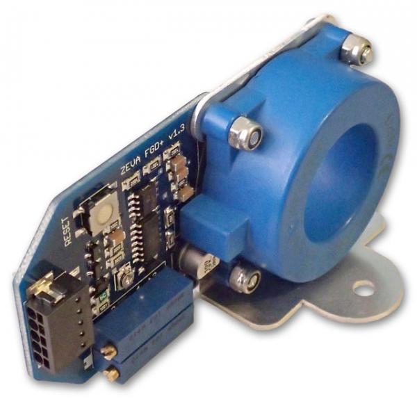
Picture of a ZEVA Fuel Gauge (  http://www.zeva.com.au/index.php?product=103  ).  This device is available from various domestic distributors.  These devices re priced between $150-$200 depending upon the features desired.

The manufacturer indicates that the ZEVA also has the ability to output a signal directly to the fuel gauge to provide an indication of the batteries State of Charge (SOC).  It also can provide a signal that can convert the instrumentation tachometer into an output of instantaneous current and thus provide an indication of real time power consumption.  One of the problems with this type of sensor, is that at under low current (or no current) situations, the measurement is not as reliable and drift can become a problem.  The device is sensitive enough that its output can vary relative to the sensor's orientation to Earth magnetic North.  12 volt power must be maintained to the device or the measurements are lost. 

A very sophisticated and new to the market device is the Electric Vehicle Interface Controller (EVIC) that is available from both Andromeda Interfaces, Inc. (  http://ai-displays.com/product/e-v-i-c-basic-enclosure/  )  and their distributors.  With a price tag of about $700, this device operates over a CAN bus and it can simultaneously display multiple parameters, including: Motor Temperature; Controller Temperature; Motor RPM;  Motor Voltage (VDC); and Motor Charge and Discharge Amperage (Amps).

Andromeda Interface for GEVCU
Picture of an Electric Vehicle Interface Controller (EVIC) supplied by the Andromeda Interfaces company. 

Alternatively an intelligent amp hour meter can be used and popular examples include the JLD-404 (Picture DSC04182) and the Xantrex LinkPro (picture below).  Each device requires a shunt to be inserted directly into the drive battery circuit.  Since these shunts are live they pose a potential shock hazard and they must be located within a protective enclosure.


Picture DSC04182 of a JLD-404 intelligent Amp Hour Meter.  These instruments are modestly priced between $70 and $120 depending in part upon the supplier and the shunt selection.  The JLD-404 can measure up to 9999 amps,  pack voltage up to 500 volts, amp hours, and time.  It also has two internal relays (NO and NC) that can be programmed to perform based upon the measurements taken by the device.  Typically 75 mv shunts are used with this device, but 50 mv shunts may also be used by modification of the set up parameters during installation.  A user manual can be found at http://evwest.com/support/JLD404AH-Eng.pdf  .


Xantrex Linkpro Battery Monitor - Splash Proof Front Panel/CE & E-Mark Certified
Picture of  a Xantrex Link Pro which is premium priced at about $275.  The Xantrex Link Pro can measure currents up to 10,000 amps, pack voltage up to 350 volts, charge and discharge current, and amp hours consumed and remaining within the pack. Owners guide can be found at  http://www.xantrex.com/documents/Accessories/LinkPro-Battery-Monitor/LinkPRO_Operation(975-0430-01-01_rev-C).pdf


The 325i build described in this blog will initially focus on the use of the JLD-404 with its accompanying shunt.  A shunt should be matched to the expected maximum current flow and it can typically range from less than 200 amps to more than 1000 amps.  Initially a 1000 amp 75 mv shunt was purchased since the Soliton 1 can handle up to 1000 amps.  The full 75 mv will be measured only when the maximum 1000 amps is passing through the shunt.  The initial testing demonstrated that on level ground and at low speeds the Warp 11 was drawing only about 25 amps and one would anticipate that the voltage drop across the shunt would be only (25/1000)x75mv=1.875 mv.   This is a very small signal and an alternate 200 amp shunt was substituted because with the same 25 amp draw, the signal would be anticipated to be (25/200)x75mv=9.375 mv.

The connections between the car and the JLD-404 are as follows:

Pin 1 will be connected to +12 house battery;
Pin 2 to house battery ground (car chassis);
Pin 5 to the +144 of the drive battery pack;
Pin 9 (which is the 75 mv input) to the shunt terminal farthest away from the drive battery ground;
Pin 10 to the drive battery - shunt terminal closest to the drive battery ground.

Prior to connecting the JDL-404 to the car, measurement with a Fluke 233 True RMS Multimeter confirmed that there is an open circuit between Pins 1 and 2 and all other Pins on the device.  This suggests that the JLD-404 power supply circuit (Pins 1 and 2) is internally isolated from the high voltage section of the device.


Picture DSC042402  showing the installed JLD-404 in operation during operation of the car.

Electrical safety is personally and financially very important.  The proof that one can build an EV in the garage, starting with a basic understanding about cars, access to the Internet, and a modest check book, would be seriously eroded if the car occupants were injured or the build itself incinerated due to electrical defects.  While attempting to visualize the possible placement of a 200 amp shunt in the fuse and relay box, accidental contact was made between both sides of the battery pack  !!  (Picture DSC04102)


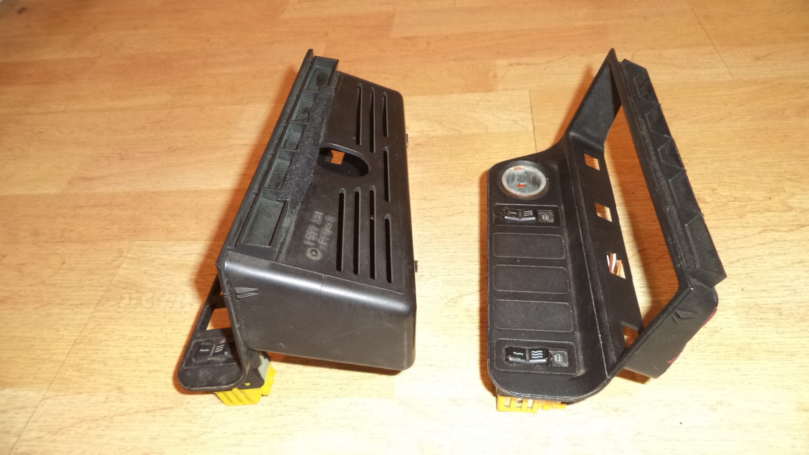
Picture DSC04102 of the damaged control and safety module.  Molten Aluminum sprayed onto the back of the passenger side front seat !!

The energy release was loud and a grey white cloud accompanied the molten Aluminum spray. The batteries do not have the characteristic gasoline smell to remind one that there is a present danger.  The addition of a master shut off within the battery pack will be desirable so that tinkering with the pack can be done safely.  Good luck did prevail as other than replacing some minor cable component parts, the expensive fuses remained intact.  The currently installed 600 amp fuses are probably more appropriate for Lithium Iron Phosphate batteries (for example CALB 180 styled batteries).  Smaller amperage fuses of perhaps 400 amps may be more appropriate when testing the Optima Yellow Tops.  Had the short circuit not blown the pieces apart and instead welded the shunt to the contact points, the final outcome of the incident might have been quite different.


Picture DSC04106 of the bottom of the shunt after the incident.


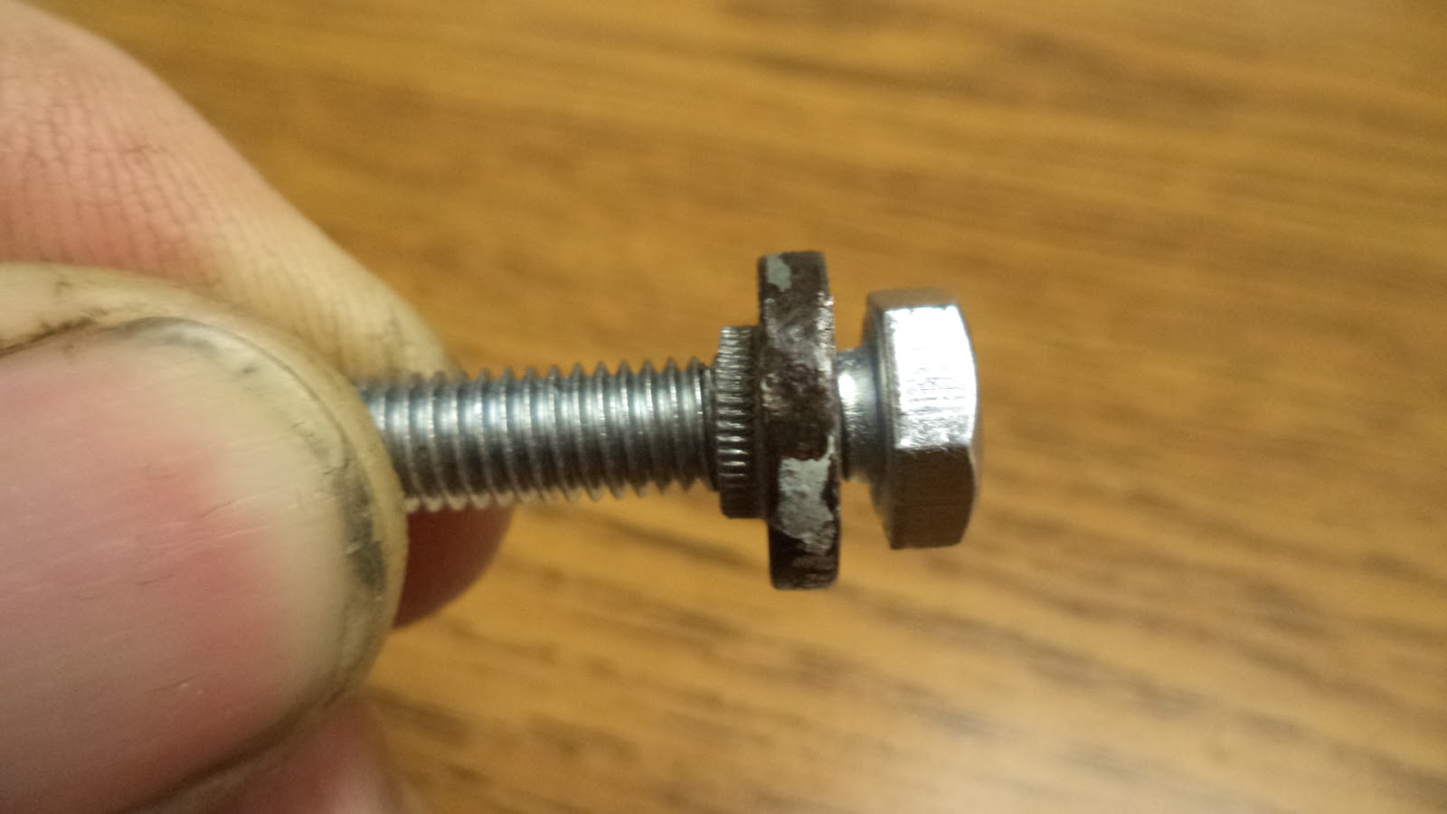
Picture DSC04105 of the top of the damaged shunt.  The small screws on the top are for connection to the 75 mv signal inputs of the JLD-404.   The damaged screw was welded to the body of the shunt and the fused metal had to be ground away prior to its replacement.  The screw appeared to be an M5 .8 x 6, but this size was not readily available, so alternatively both screws were replaced with an M5 .8 x 8 along with a #10 stainless steel washer.

The JDL404 requires a shunt that is in series with the pack voltage circuit and it must be isolated from the chassis and protected from accidental contact with tourists.  The control and safety module currently located in the back seat provides both of these requirements.  It was elected to place the shunt on the ground leg of the pack circuit, and a space very similar to the length of the shunt was available between a relay and its corresponding fuse.    Since this space was initially the positive side of the battery circuit, the wiring was switched so that the space available became the ground leg.  See pictures DSC04110 and DSC04111.


Picture DSC04110 top view of the installed 200 amp 75 mv shunt in the control and safety module.  Previously the foreground circuit was positive voltage (picture DSC04102), but since an ideal space was present in which to place the shunt, the circuits were exchanged


Picture DSC04111 of a side view of the installed 200 amp 75 mv shunt in the control and safety module.  The 200 amp shunt mounting holes are 3.375" apart, while the 400 and 1000 amp shunts have mounting holes that are 3.9375" apart.  Since the fuses and relays are mounted using a strut channel, it is very simple to relocate the fuse (foreground) to accommodate shunts of different lengths.

Shunts

A shunt allows the measurement of the current flow provided by the pack and when coupled with a pack voltage measurement, it can provide a measurement of total power use (or alternatively when charging the pack, the degree of battery charge). 


DSC05774 of a 75 mv 400 amp shunt. (updated 4/3/17)

Picture of a 75 mv 200 amp shunt.  Two black elements connect both posts.  Initial tests of the Lead acid batteries while driving at modest speeds on level ground suggests that 25 amps was all that was being consumed.  For higher performance testing, and especially with Lithium Iron Phosphate cells, a 400 amp or 600 amp shunt will be substituted later.


Picture DSC04218  of a 400 amp shunt showing four conducting black elements.


Picture DSC04215 showing the method used by the manufacturer to calibrate the shunt by equally reducing the cross sectional areas of each black conductive elements with a saw.

Ammeter Ammeter 1000A 75mV DC Current Shunt Resistor

Picture of a 75 mv 1000 amp shunt.  For this style of shunt each of the ten black elements passes 100 amps.  Each black element is actually a 75 mv 100 amp shunt, and in principle one could make a custom shunt if needed.  For example, by cutting away one of the black elements, one would make a 75 mv 900 amp shunt.

Fuses for JLD-404 connections

Each of the three electrical leads connecting the shunt to the JLD-404 were fused using panel mount fuse holders  (  http://www.mcmaster.com/#7087k15/=yb2si5  ) along with 0.25 amp ceramic fuses (  http://www.mcmaster.com/#71385k21/=ygp4x7  ).  The fuse holders were designed for 0.125" thick panels, but were easily modified using a screw driver to remove a plastic spacer so that they then fit nicely with a 0.250" panel.


Picture DSC04123 showing the fuse assembly as initially received (top) and after removal of the plastic spacer (center at right), and final assembly to make the fuse holder compatible with a 0.250' thick panel.


Picture DSC04136 showing on the left the fully insulated Quick-Disconnect Terminal, 0.25" W x 0.032" Thickness Tab  (   http://www.mcmaster.com/#7243k11/=yb37oj  ) for attachment of the wires to the tabs on the fuse holders.  On the right is a Ring Terminal, 5/16" Screw Stud Size  (  http://www.mcmaster.com/#7113k733/=yb381i  ) for connection of a wire from the fuse holder to the +144 volt input of the Kilovac relay.  Very small AMP Spade Terminals (22-18) were required to make the connections on the back of the JLD-404 .


Picture DSC04131 of the end plate of the battery safety box.  Both sides of the shunt (ground and 75 mv outputs) as well as the pack voltage reference wire were fused to 0.25 amps.  The high voltage reference wire (McMaster part 8054T811) is an 18 gauge wire that is rated 600 volts.   After this picture was taken the ground wire was later moved from the center to the far right, and the 0-75 mv wire was moved from the far right to the center.


Picture DSC04220 showing the inside view of the three 0.25 amp fuses that were inserted into the circuits prior to connection to the JLD-404.  


Picture DSC04219 of the top view of the control box.  The battery pack enters from the left and then  passes through a pair of 600 amp fuses.  The negative (or ground leg) cable in the foreground then passes through a 200 amp 75 mv shunt which is then connected to the input of the control relay.  The yellow connections are on the top of the shunt.  The pair of yellow tabs on the left (shielding braid and the cable black wire) are connected to the input of the shunt, while the yellow tab on right side (small red wire) was connected to the output of the shunt.  These wires were then routed through a pair of fuses located on the left wall of the box prior to being connected to the JLD-404.   At the top center of the picture can be seen a small blue wire that provides pack voltage to the JLD-404.  This wire is connected to the relay input post and after passing through a fuse on the left wall, it then is connected to pin 5 of the JLD-404.


Tuesday, August 11, 2015

Installation of BMW throttle body and its connection to the Soliton 1

The BMW throttle body is directly connected to the driver's accelerator pedal on the floor.  It has a cable linkage that moves the vane within the throttle body and simultaneously rotates an attached three wire rheostat (throttle position sensor).  If a voltage is applied across the potentiometer, then a movable wiper will output a voltage that is dependent upon the position of the wiper. 

The Soliton 1 can accept a 0-5 volt DC signal when applied to the terminal labeled "Throttle", where +5 volts is considered to be "full throttle".  The Soliton 1 can accept signals from other potentiometer type devices such as a Hall effect device, the Evnetics throttle transducer, and in principle even the BMW throttle body potentiometer itself.  This last solution has merit in that the throttle body potentiometer can be salvaged from the donor car's engine at no additional cost and the cable linkage is already established between the pedal and the throttle potentiometer!  The cruise control actuator is also connected to the throttle body, thus it may be possible in the future to also include the cruise control option in the final EV conversion.  

Evnetics Throttle Body


Picture of the Evnetics throttle assembly.

When using the Evnetics throttle body (picture above) the red wire is connected to the Soliton 1 terminal labeled S5V, the black wire is connected to the Soliton 1 terminal labeled SGND, and the white wire (wiper) is connected to the Soliton 1 terminal labeled THROT.  During operation the throttle body output was measured to be 0.396 volts DC when at 0% throttle, and 4.346 volts DC when the throttle was at 100%.  Calibration of the throttle is completed according to the instructions provided on page 23 of the owners manual (  http://www.evnetics.com/downloads/Soliton_Manual_1v4_rev2.pdf  ). 


BMW Throttle Body and Potentiometer

One of the biggest challenges regarding using the BMW throttle body and potentiometer is determining where and how to mount the oddly shaped mechanism.  To further complicate the task, the cable feed from the accelerator pedal only extends from the firewall about 17 inches into the hood area.  One possible solution is to use the driver side engine mounting bolts to secure a platform that is elevated above the mounts and sufficiently close to the firewall that no cable modification is required.  The mounting surface described in a previous posting was predrilled and the holes tapped to accept 1.5" long hex head 1/4" 20 bolts (picture DSC04253).


Picture DSC04253 which shows the mounting surface measurements and the four holes that were tapped to mount the throttle body.  


Picture DSC04254 of the secured OEM throttle body on the mounting plate.


Picture DSC04257 view from the top of the mounted throttle body and mounting plate.  The multiple red (temporary) butt splice electrical connectors at the top center of the picture were used to connect the three wires from the BMW OEM throttle body to a three wire cable that was connected to Soliton 1 terminals SGND, S5V, and THROT.  For simplicity, in this picture the cruise control cable has been removed.  On the left side of the picture is what remains of the original OEM wiring harness that remained after the ICE was removed.  These wires are gradually being separated out and those that are not necessary to the build are being eliminated. 

The BMW throttle body uses a three pin female socket (picture DSC04262  ) and the corresponding OEM plug that was retained from the donor car wiring harness is shown in picture DSC04261.  


Picture DSC04262 of the connector located on the side of the BMW throttle position sensor.  Pin 1 is to the far left, pin 2 is in the middle (wiper),  and pin 3 is to the far right.


Picture DSC04261 of the connector salvaged from the ICE donor wiring harness.  Pin 1 is to the far left and is attached to the brown output wire, pin 2 is in the center and is attached to the brown/black output wire (this is the wiper) , and pin 3 is to the far right and it is attached to the  red/yellow output wire.

To connect the outputs of the BMW throttle position sensor to the Soliton 1, the Red/Yellow wire (pin 3) is connected to the Soliton 1 terminal S5V, the Brown/Black wire (pin 2) is connected to the Soliton 1 terminal THROT, and the Brown (pin 1) throttle position sensor wire is connected to the Soliton 1 SGND.   During operation the throttle body output was measured to be about 0.643 volts DC when at 0% throttle, and about 4.368 volts DC when the throttle was at 100%.  Calibration of the BMW throttle was then completed using the same process as was used for the Evnetics throttle body.  Additional test drives of  the 1992 BMW 325i EV conversion has shown that the accelerator (or "gas pedal") now behaves in the same way as the original ICE donor car !!

On first attempt it was interesting to discover that when the connections between pins 1 and 3 were reversed, the car's accelerator pedal behaved quite differently.  If the car's accelerator pedal was fully pressed to the floor, the motor was off, and when the foot pedal was fully released, the motor was at maximum acceleration!  It would be a stressful driving experience if all cars on the road were to use this inverted throttle configuration !!!

Butt splice connectors were initially used (picture DSC04257) when wiring the test circuits, but the trial and error process was made easier when fully insulated 0.250 Tab male and female terminals were used instead (picture DSC04264). 


Picture DSC04264 of the disconnect 0.250 tab disconnect terminals (female on left, male on the right) that were used.  

Tuesday, August 4, 2015

Engine Support - Welding Stud Repair


Picture DSC02190 front view of the damaged M6 stud (upper right).  This welding stud sheared off during removal of the grill nose panel and bumper.  This structural element appears to be called the "left engine support" and the BMW dealership indicates that to repair the stud requires the purchase of the entire support!  The left engine support is part # 3 at :  http://www.realoem.com/bmw/enUS/showparts?id=CB33-USA-08-1992-E36-BMW-325i&diagId=41_0043  .


Picture DSC02193 rear view of the left engine support showing the wide stud heads
.


Picture DSC03921 of the opening created after the stud popped out during the attempt to drill and tap an M6 hole.  If the process had been successful, it was hoped to thread in an M6 bolt and then weld the bolt head to the engine support.  If any reader knows where these welding studs can be obtained, please leave a comment or send an email if you are willing to share the information.  The hole did accommodate the use of a M8 x 30 mm bolt along with a backing washer and nut.  Unlike the welding stud, this solution requires the use of two wrenches when attaching the front bumper.


Picture DSC03922 showing the serrated edge of the BMW welding stud after it was dislodged from the frame (D = 8.10 mm).  This picture is of the base of the stud after the broken stud was cut off and knocked out of the chassis.  The head of the BMW welding stud is 0.55" (13.90 mm) at its widest point (left to right in above picture), and the serrated area that passes through the sheet metal is 0.317" (8.05 mm) diameter.  The BMW stud head is  0.1185" (3.01 mm) thick (top to bottom in above picture) and the serrated area contributes an additional 2 mm of height. 

Another option would be to repair the original stud by drilling and tapping an M6 threaded hole that would then accommodate a 30 mm stud (or bolt).  The stud would then be welded to the tapped head and the repaired "welding stud" then pressed back into the engine support.


Picture DSC04097 of the drilled and tapped head of the BMW welding stud.


Picture DSC04096 of the back side of the welding stud base after the paint had been removed with a wire brush.  The markings seem to indicate "ABC 8.8".  


Picture DSC04101 side view showing the 30 mm M6 bolt fully inserted into the threaded BMW welding stud head.  The bolt is not threaded to the base of the hex head, so a gap remains.  To prevent the bolt from rotating during installation of the bumper, the two pieces can be tack welded together prior to being pressed back into the face of the engine support.


Picture DSC04100 of the front view of the assembled "repaired" welding stud prior to trial fitting it in the car.

An alternative solution was created by David in which he used his lathe to machine an M6 1.0 x 30  bolt so that the head was reduced in height and a collar was created.  The collar section can then be pressed into the opening on the engine support.


Picture DSC03999 side view of David's machined "welding stud" that he made from a M6 1.0 x 30 bolt.  One half of the head height was turned down to a diameter of 0.302".  This diameter can then be press fit into the engine support followed by welding the head to the engine support.  The head was also rounded to remove the original hex points and produce an outer diameter of  9.77 mm.


Picture DSC04038 before and after end view of the  M6 1.0 x 30 bolt that was converted into a "welding stud". 

Monday, August 3, 2015

Installation of a Mounting Surface for the BMW Intake Throttle Body

The throttle body in the ICE is attached to the gasoline engine's air intake and the mechanism is directly connected to the driver's accelerator pedal on the floor.  When the accelerator pedal is depressed, a cable linkage rotates open an internal vane within the throttle body to permit greater air passage for greater combustion.  As the vane rotates,  the shaft of a three wire potentiometer simultaneously rotates and a changing signal voltage is supplied to the engine computer.  Alternatively this same voltage signal could be supplied to the Soliton 1 and used as an electronic throttle.  The cruise control is also attached to the same throttle body vane, and if one can use the OEM device from the original donor car, then one may be able to both save the cost of a new throttle body and possibly incorporate the cruise control into the final EV build.

Using the BMW throttle potentiometer poses a problem in terms of how to mount the oddly shaped throttle body as well as where, since the cable within the motor compartment only extends about 16 inches from the firewall.  One possible solution that will be tested with this 325i build will be to utilize the driver side engine mounting bolts to create a mounting platform that is both elevated above the motor  mounts and sufficiently close to the firewall so that no cable modification is required.   

Installation started with a 12" long section of  6" x 6" x 0.25" x 6061 Aluminum 90 degree angle (McMaster 8982K46, $37.46).  The mounting bracket and lifting arm of the driver side motor mount was then removed from the car and matched to the 90 degree angle on the bench top.


Picture DSC04183 of the  6" x 6" x 0.25" x 6061 Aluminum 90 degree angle before machining.


Picture DSC04190 side view of the modified Aluminum angle shown in picture DSC04183 above.  Note that the notch was cut away  to allow the motor mount strut to pass through the plate.  The cuts were made initially with a 1.6 mm abrasive cutoff wheel in a Ryobi grinder to notch the Aluminum (this prevented the Sawzall blade from jumping off the cut line), followed by a rough cut with a metal cutting blade in a Sawzall, and finally the cut surfaces were smoothed with a metal file. 


Picture DSC04193 oblique view that shows the width of top surface was reduced from 6" to 4" to prevent the top surface from contacting the Warp 11 clam shell mounting hardware.


Picture DSC04194 showing the mounting bolts reversed and protruding in preparation for the addition of the mounting platform.


Picture DSC04196 top view of the mounting platform in place.  Note that there is a gap between the edge of the new mounting platform and the existing clam shell style Warp 11 motor mount.


Picture DSC04197 showing oblique side view of the mounting platform.  Note that the motor mount strut fits nicely through the notch that was cut from the side of Aluminum angle.  


Picture DSC04202 trial fitting of the  throttle body.  For ease of manipulation, in this picture the cruise control cable was temporarily disconnected from the throttle body vane mechanism.


Picture DSC04212 showing an alternate trial fitting in which an electric power steering pump is placed forward of the lighter weight throttle body.  Note that the length of cable within the motor compartment is long enough to permit the throttle body to be located anywhere on the platform.

Sunday, August 2, 2015

Control Panel and JLD404 Installation into the Center Console


Picture DSC04165 of the center console after removal of the Multi-Information Display Module and removal of the console from the car.  The Storing Partition Insert is still in place.


Picture DSC04166 front close up view of the Storing Partition Insert which includes the lighter and seat heating controls.


Picture DSC04159 of the BMW center console after removal from the 325i.  BMW calls these parts the Storing Partition (bottom and dark tan color) and the Storing Partition Cover (top section of black trim).


Picture DSC04112 showing the flexible rubber mat (left) after it was removed from the base of the plastic part (right).  Pushing the four tabs on the front underside of the opening (both backward and up) allows the tabs to snap free.  BMW calls the complete part the  Storing Partition Insert.


Picture DSC04114 showing the part before removing the rear storage section (left) and after the plastic had been cut away (right).


Picture DSC04115 showing an oblique view of the Storage Partition Insert after removal of the rear plastic.


Picture DSC04145 showing the three inserts (BMW calls them a Cover)  removed from the base.  It was hoped to install a switch in each insert, but the inserts were too narrow, so a black anodized aluminum plate was prepared that covered all three openings at the same time.


Picture DSC04155 showing the 0.125" thick black anodized Aluminum plate (McMaster 7083T21) after it was cut down to 3" x 1.75".  Four mounting holes to accept M5 .8 x 20 bolts are located 0.250 inches from top (bottom) and the sides (left or right).  The plate was then drilled (12 mm) to receive three illuminated SPST toggle switches (20 A, 12 VDC) that will control:  (1) activation of the pack relays (blue); supply +12 volts to energize the Soliton 1 (green); and supply +12 volts to the JLD-404 Amp Hour Meter (red).  Other functions may later share the use of these switches.


Picture DSC04154 of the bottom side showing the temporary nuts that secure the Aluminum plate to the BMW plastic part.  An Aluminum strip will later be added as a backing plate in lieu of using separate washers with each M5 .8 x 20 mm bolt.


Picture DSC04170   of the black anodized plate that was cut to cover the recessed opening of the Storage Partition Insert.  The overall plate was 2.6875" x 7.4375" x 0.125" and the opening for the JLD-404 meter is 1.6875" x 3.625".


Picture DSC04169 of the mounting plate with the JLD-404 installed.  Four mounting holes were next drilled, each 0.50" from the top(bottom) and side edges.


Picture DSC04181 showing the 3/4" x 3/4" x 1/16" right angle Aluminum pieces ( 2.75" long) that were used as backing plates along with machine screw nuts to secure the plate holding the JLD-404 to the Storage Partition.


Picture DSC04178 of the mounted JLD-404 in the mounting plate, secured to the Storage Partition Insert, and installed in the center console.  Initially #6-32 x 1.5" machine screws with fiber washers were utilized as they were on hand, but they will eventually be replaced with black screws to improve overall cosmetics.