Considerable mental energy has been expended regarding the problem of connecting the rear battery pack to the front battery pack. Several goals are desired: (1) protecting the rubber insulation of the cables from mechanical damage; (2) isolating the voltages from water (rain or standing water in the roadway); (3) physical placement of the cables as close together as possible to minimize the creation of magnetic fields; and (4) placement of the cables within a shielded conduit, or channel, or metal braid, or copper tape, to minimize the radiated electric fields.
Examination of the underside of the car suggested a pathway adjacent to the power brake lines on the left side of the car. This area is very slightly recessed into the base of the car. The outer diameter of the rubber insulation of the battery cables is about 1.5 cm. The rubber would protrude below the base of the car and it would be vulnerable to potential damage from road debris. If the cables coursed through in an Aluminum or Steel channel for protection, then the pathway would still be the lowest point of the undercarriage, and water would tend to collect within the structure. Placing regular openings in the channel to allow drainage, then exposes the rubber to potential damage. The placement of each cable in separate metal conduits suggests an advantage since the conduits could be custom bent to rise up into the motor and the trunk compartments. The addition of bulkhead fittings could make the system relatively water tight. Unfortunately, placing each cable in separate metal conduits may induce a current in the conduit in the space between the two wires and this could result in the heating of the conduits. The field forces on the wires may also cause movement of the cables within the conduits and eventual chaffing of the insulation over time. With these observations in mind it was elected to study how BMW routes the OEM battery cable from the trunk to the motor compartment.
DSC01288 showing the view looking forward of the OEM battery cable as it disappears into the front right bulkhead wall of the trunk. The cable passes through a black rubber gasket which is seated in the punched out metal wall.
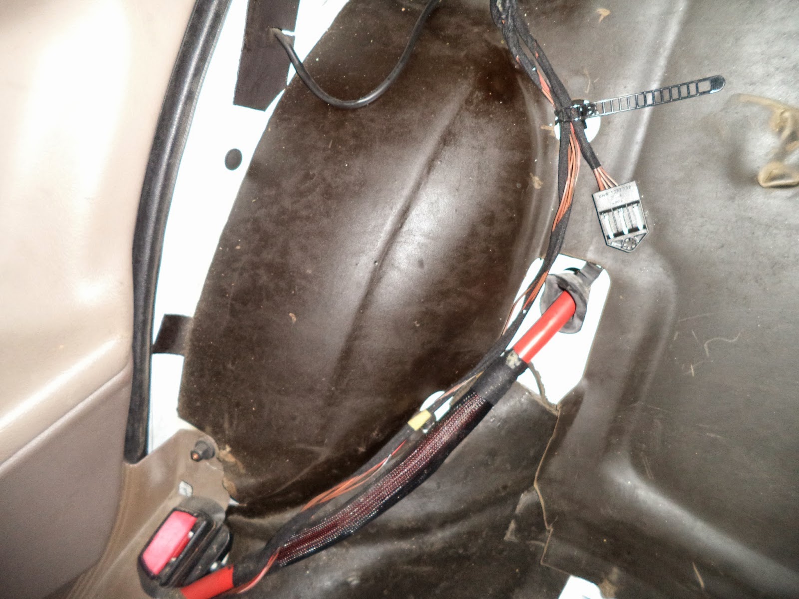
DSC01289 after removal of the back seat this view shows the battery cable as it enters the cabin to the right of the right rear wheel well and descends downward toward the seat belt clip. There is a 10 inch plastic woven sleeve over part of the cable. The process for removal of the rear seat elements will be posted later.
DSC01290 showing the battery cable entering under a tan colored plastic trim by the side of the seat and the base of the door. The black plastic nut adjacent to the seat belt clip (right) was next removed.

DSC01311 showing the chassis hardware after its removal from the frame (hole in center of picture) using a pair of pliers. This hardware also serves to lock the floor carpet into place. The plastic trim piece must be moved sideways to disengage it from the chassis hardware. Picture DSC01330 shows the underside of the plastic trim piece and the slot that engages the chassis hardware.

DSC01330 showing the shape of the sliding portion of the underside of the plastic trim. There are (or were) two of these on this trim piece.
DSC01296 after removal of the plastic trim guard. This trim piece is removed by sliding the plastic trim piece backwards and sideways. See picture DSC01311 and DSC01330 for details.
DSC01314 showing the descent of the battery cable into a tunnel created by black protective plastic trim elements. Since it is intended to replace the stained carpet during the EV conversion, a shop knife was used to excise the flooring carpet that obscured the path of the battery wires. This view is from the front looking back at the passenger seat. The large round opening at the center right was previously the access point to the ICE fuel tank and fuel pump.
DSC01315 showing the route taken by the battery OEM cable. View is from the back seat looking forward to the front of the car. The structure to the top left is a ventilation duct that originates from under the carpet that covers the center console. All of the black components were hidden under the carpet, and due to a layer of rubber foam that was bonded to the underside of the carpet, there was never any previous awareness that these utilities were hidden in this way.
DSC01328 after the plastic "tunnel" pieces were removed all that remained was the ventilation ducting.
Picture DSC01320 demonstrating the trim tool that was used to carefully pry out the plastic retainer that secured the ventilation duct to the floor. The stud at the top left previously held the front left frame of the passenger seat.
Picture DSC01331 of the pathway under the cross brace. It is hoped that there is sufficient room adjacent to the OEM battery cable to route two additional battery cables through the frame.


This comment has been removed by a blog administrator.
ReplyDelete