Sunday, October 21, 2012

Brake Systems 2.0


After further consultations, additional replacement parts for the brakes have been ordered.

Meanwhile, this last week, a 12 volt vacuum pump arrived that will be used to replace the lost manifold vacuum previously available from the now extracted internal combustion engine (ICE).  The pump selected was model MES 70/6E and it was purchased ($301) from Metric Mind Corporation (http://www.metricmind.com/category/ev-vacuum-pumps).  It weighs about 1.2 kg and it has a operating noise level of about 58dBA.  It  purrs with a sound level that is very much like a  aquarium air diaphragm pump.  The manufacturer indicates that a 3 amp automotive fuse must be used for the electrical protection of the pump.


Picture DSC 05088 shows the side view of the MES 70/6E.  It is designed to be run with the long dimension oriented parallel to the base of the car.


Picture DSC05089 shows the top view of the MES 70/6E.  There are 3 mounting holes on the base that have rubber/grommets with brass centers to secure the pump to the vehicle.

This pump was highly recommended by Tim Catellier (http://www.evalbum.com/3189 ) and it was shipped immediately by Metric Mind upon placement of a credit card order.    For an additional $8 Metric Mind included a connector plug kit which requires both additional wires as well as the attachment of crimp/solder pins to the leads before it can be used.


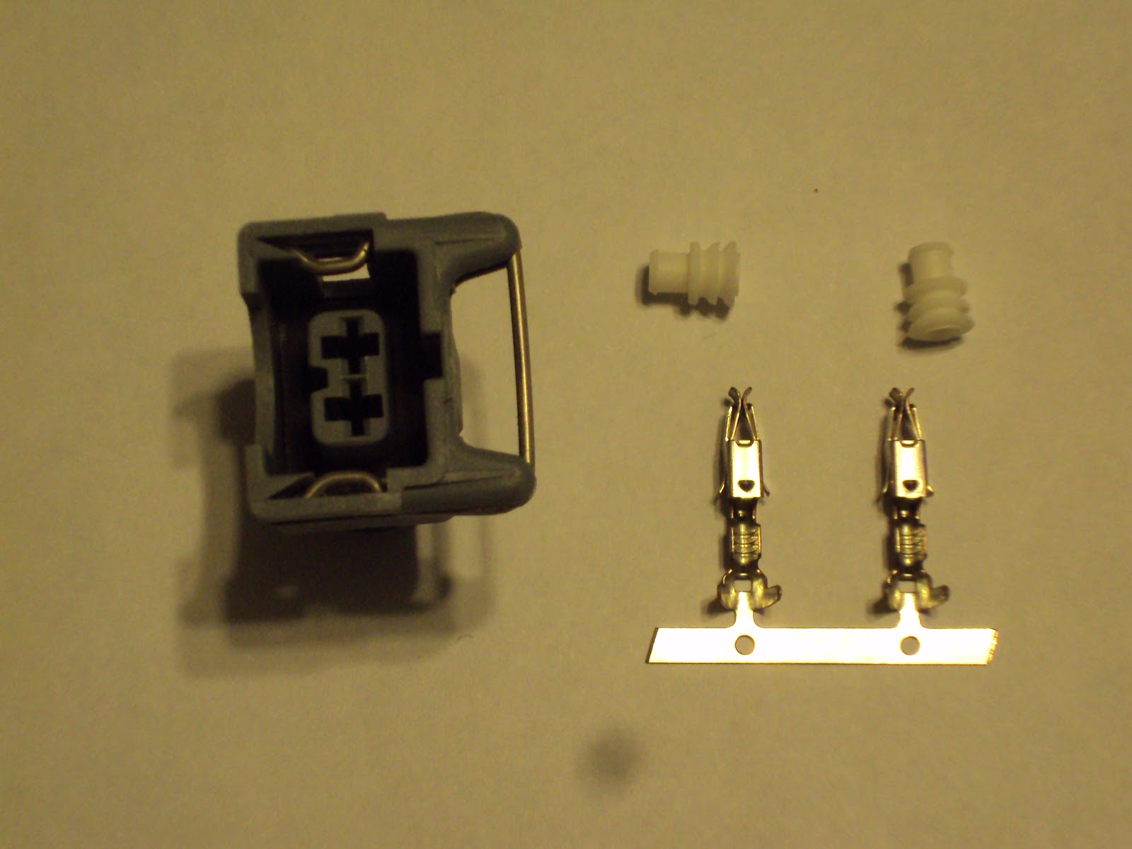
Picture DSC05075 that shows the wiring plug kit that required assembly before being used.


O'Reilly Auto Parts offers an equivalent prewired plug with 7” wire leads as part BWD 28423 ($6.99) that was purchased for initial testing with a 12 volt battery. 


Picture DSC05086 showing the O'Reilly Auto Parts previously assembled electrical plug that is compatible with the MES 70/6E electrical connections.

Using a research grade vacuum gauge (McMaster Carr part 4105K24) the ultimate vacuum under normal operating conditions was measured at 19.8 inches (495 mm) of Mercury. At this vacuum the pump's internal pressure switch automatically shuts off and then later restarts when the vacuum quality has decreased to 18 inches (457 mm) of vacuum. When the power leads were reversed (per manufacturer’s instructions for temporary testing in a “diagnostics mode”) the ultimate vacuum achieved when the pump ran continuously was 21 inches (533 mm).  The vacuum range delivered by the MES 70/60E is claimed by the manufacturer to be identical to the vacuum produced with a typical ICE.


Picture DSC05087 showing research vacuum gauge that was used to measure the operational and maximum vacuum produced by the MES 70/6E vacuum pump.
 

Tuesday, October 16, 2012

Foundry Castings Returned from the Machinist

Today we picked up the finished adapter plates from the machine shop.  These adapter plates were first reported in this blog 8/16/2012, and now two months later, we have them in hand.  The first three foundry castings were made from David's foundry mold and then a machinist used David's engineering CAD drawings for the bolt and motor placement holes.  We now have the ability to produce these adapters on demand if other EVers need them.   The next step will be to build the drive train and confirm that bolt holes and dowel tube placements are precisely where they should be.


Picture DSCN0541 showing casting after face machining, pushed against large faceplate with live center in tail stock.


Picture DSCN0889 showing active drilling of holes after CNC machine setup and programming.


Picture DSCN0909 showing finished machined surface from the Getrag transmission side view.  The holes   drilled for 14.5 mm orientation dowel tubes are located at about 11:30 and 7:00 (toward mid line).
Holes are 14.5 mm ID and 6.62 mm deep.  

(updated 4/22/2021)


Picture DSC01132 of the Aluminum dowels (2 required).

Dowels were purchased from BMW (part 11117524470 and $1.65) and were Aluminum with a 14.50 mm OD x 12.56 mm ID and 10.72 length.  The edges were beveled on the outside lip.


Picture DSC01134  showing the placement of the pair of 14.5 mm dowels on the transmission side of the adapter plate prior to using a mallet to force them into place.  A full thickness 12.6 mm pilot hole was initially drilled, followed by a 14.5 mm dowel hole that is 6.62 mm deep.  This created an internal  stop so that the dowel cannot be over inserted.


Picture DSCN0910 showing finished machined surface from the motor (Warp 11) side view.  Note that there are 12 mounting holes in the center polished surface.  These holes will allow the Warp 11 to be rotated into a variety of orientations.


DSC01669 side view of the adapter plate.


DSC01671 transmission face side.


DSC01672 motor face side.


.

Wednesday, September 19, 2012

The "Build" - Final Keyway Design - Part 2 (Final)

Today was a very good day !  At the previous initial build attempt it was found that the Warp 11 being used in the build had an obsolete motor end plate.  This older design end plate prevented the hub adapter from fully inserting into the face plate as required.  After the end plate was replaced and the hub adapter correctly installed, the critical dimension was no longer valid and John Emde at Pioneer Conversions had to precisely reduce the thickness of the spacer ring with his lathe.  After reduction of  the thickness of the spacer, and reassembly of the adapters, the critical dimension was restored.


Picture DSC05031 showing the now thinner spacer located between the end plate of the Warp 11 and the transmission adapter plate.  Note that the hub adapter shaft is now nearly fully inserted into the adapters.


Picture DSC05030 showing 35.9 amps current draw when bench top tested with a 12 V shop battery.  The motor just purrs and you can hardly tell it is even running.  Essentially no vibration!


Picture DSC05032 demonstrating the insertion of the plastic clutch plate centering tool into the bronze bearing for the  proper positioning of the clutch plate.


Picture DSC05033 showing the full clutch assembly with the clutch plate internal and the pressure plate externally secured with 6 socket head bolts.  When running the full clutch  assembly with a shop battery there is a very slight vibration.  John indicates that this will disappear when the transmission is installed in the car and the floor clutch pedal is pushed in.  The clutch pedal will at that moment dislodge the clutch plate from the pressure plate and allow it to precisely center itself on the flywheel.


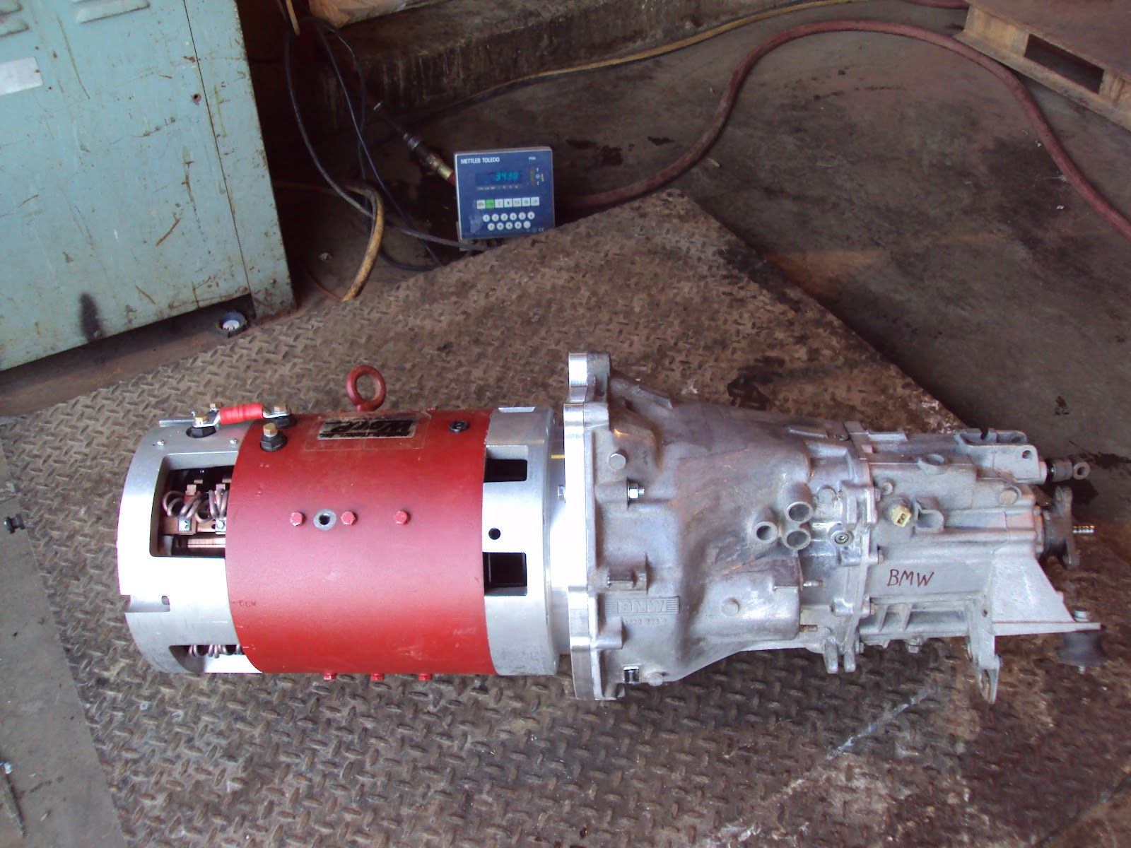
Picture DSC05037 showing the fully assembled drive train weighing in at 343 pounds.  The drive train includes the Warp 11, hub and transmission face plate adapters, flywheel, clutch plate, pressure plate, and the Getrag transmission.

The next step is to lower the unit into the motor compartment and take measurements for the design of the motor mounting adapter that will stand on the recently replaced rubber engine mounts.


Sunday, September 16, 2012

Brake Systems 1.0 / Motor Mounts 1.0


Brake Systems 1.0


The 1992 BMW 325i has four wheel disk brakes in addition to a parking brake.  The parking brake is internal to the rear rotors which have an integrated parking brake drum.  The 325i was placed on jack stands, the wheels removed, the brake lines drained, and all of the brake calipers/pads removed for inspection.  Next time a small flat head screwdriver should be used to separate the rear right pad sensor wire from the pad. Attempting to instead remove the sensor by pulling on the wire lead now requires that the part be replaced.  The left front wheel does not rotate freely and it has a grinding noise. All of the wheels must rotate freely to minimize the load on the future battery pack.

The front brakes look good, but the rear pads are to bare metal..  The rear rotor thickness ranged between 9.12 mm and 9.20 mm and Bentley suggests a minimum thickness of 8.4 mm, so these are good to go.  The front vented rotors are slightly above the minimum suggested by Bentley of 20.4 mm, so these will need to be replaced in the near future.  Mounting screws on the rear brakes were then removed and the rotor/drum loosened with a mallet and pulled from the drive flange.  Internally the passenger side parking brake shoes were worn out and all the parts completely rusted, but interestingly, on the driver’s side there were no shoes or internal mechanism !!  Only the parking brake actuator was hanging from the backing plate !! Apparently, in a previous “brake job” the technician elected not to return or replace any of the parts inside the drum !!   Instinct has been to check out each system, and now it is clear that this strategy is a must as the build moves forward.  A hardware rebuild kit and replacement brake shoes will be ordered next week along with backing plates since they both show damage at the spring retainer bolt holes.
 

Motor Mounts 1.0


The replacement OEM rubber engine mounts arrived this last week from RM European (http://www.rmeuropean.com/search.aspx?keyword=603820).  The damaged and old ones are out and the new ones are in. 
 

                         Picture DSC04988 showing top (left) and bottom (right) mounting points.


Picture DSC04989 showing side view of Corteco 603820
 
The original engine mounting brackets have been cleaned and painted, and an attempt to install them will be made after the drive train is lowered into the motor compartment and bolted to the drive shaft.  On that topic, a phone conversation with Pioneer Conversions last Friday suggested that the assembled motor/adapter/transmission may be ready for pick up on 9/18/2012.  A true milestone when it arrives! 

Thursday, September 13, 2012

The "Build" - Final Keyway Design - Part 1


I made a morning appointment and today took all of the parts and adapters to Pioneer Conversions for the official “build” of the drive train.   As in all projects, there are speed bumps.  Initially, the hub adapter would not slide fully onto the shaft, but Pioneer expertly pressed the bronze bushing a little further into the hub and it seated perfectly.  Then it was realized that the end plate on the Warp 11 motor that I purchased was an older design with a smaller 1.400 inch center opening.  This compares to the newer versions of the Warp 11 that have a 2.300 center opening.  Since the hub adapter as received has a diameter of 2.00 inches and it was designed to be recessed into the face of the newer version of the Warp 11, the build thus screeched to a halt in less than 45 minutes!!
 
It is frequently true that a man’s luck is proportional to the number of people that they have the privilege of knowing.  In my case, George Hamstra of NetGain Motors (the creator of the Warp  motors), had agreed to meet with me at Pioneer Conversions to watch the build.  He immediately got on the phone and confirmed that the modern style motor end plate was in stock at the factory, which was just a short drive from Pioneer Conversions.  We got in the car, drove to the factory and picked up the replacement end plate, a quick lunch, but, by the time we returned to Pioneer Conversions, it was too late to continue work.  So, I needed to reschedule.
                    

                               Final Design of the 1992 BMW 325i Drive Train Assembly

Moving from left to right:  the armature shaft passes thru the bearing, then thru the 2.300 inch opening of the Warp 11, followed by insertion into the hub adapter.  The hub adapter flange is drilled to accommodate the flywheel.  Located on the spline and sandwiched between the flywheel and the pressure plate is the clutch disk.  To the immediate left of the spline, the pilot of the transmission rests within the bronze bushing.  The critical dimension is marked and labeled at 0.795 inches.  To the far right is a crude rendition of the outline of the Getrag transmission housing.  Please feel free to contact us if you have any questions about the drawing.

Friday, August 31, 2012

Modifications of Original Transmission Adapters


                                                              Picture DSCN0848-2
Although this modification does not effect the performance of the adapter, it was decided to improve the cosmetics of the motor face side by using the mill and running a 4" diameter fly cutter over the full face of the plate.  Three separate passes, each time removing 0.001" of metal, yielded a surface that, after a final light Scotch Brite application, demonstrated a very pleasing nearly mirror like finish.  Compare to Picture 4790 below (originally posted on 7/28/2012).  To compensate for this reduction, the centering ring was also thinned by an equivalent amount.  The outer surface of the spacer ring was also turned in the lathe to improve its appearance.  A total of about 4 hours was spent to achieve these results.


                                                                      Picture 4790
                             Picture showing the original transmission plate adapter as received.


Thursday, August 30, 2012

Warp 11 Motor Face Modification

The hub adapter as supplied by Pioneer Conversions in Lemont was designed to fit the stock Warp 11 shaft without any modifications, and dimensionally to work with the aluminum adapter set that was also supplied by their contractor.  By contrast, the compression hub adapter that we are developing is designed to utilize as much shaft length as possible.  To allow this newer design, it was necessary to relieve a portion of the end plate of the Warp 11. 
 
To achieve this, the motor was stood on end and a Vice Grip pliers was attached to the opposite end of the shaft over a protective layer of duct tape (don't want to scratch the metal shaft).  The 8 cap head bolts were then removed from the motor and the end plate easily removed to reveal both the internal motor bearing and the cooling fan.


                                                                  Picture DSC0481
Picture showing the placement of the vise grip pliers to stabilize the shaft during removal of the end plate.


Picture DSC0844
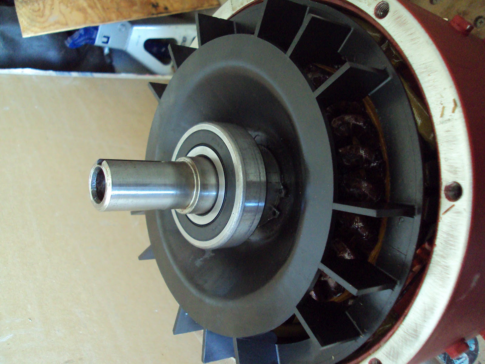
Picture showing the motor internals after removal of the end plate.  Motor bearing is visible directly next to the black cooling fan.


                                                                   Picture DSC04846
Picture showing the original Warp 11 drive end motor face after removal from the motor and prior to modification.


                                                                 Picture DSC04855
Picture showing closeup of the original Warp 11 motor face at the drive end prior to modification. The motor face as supplied by NetGain has a specification 3.997-4.000 inch diameter (ours was delivered with 3.999) and the pilot boss specification is about 0.5 inch high.  The outer diameter of this elevation inserts into the donut spacer of the transmission adapter, which should be slightly above 4.000 inches. 


                                                                  Picture DSCN0835
Picture showing Warp 11 motor face after machining a 3.2 inch diameter and 0.375 inch deep recess.  We needed about 0.25 inch clearance for our design.  The purpose of this recess is to allow the 1.57 inch long concentric adapter to fully grip the shaft without falling on the chamfer at the end of the Warp 11 shaft.


                                                              Picture DSCN0835
Picture showing a closeup view of the machined recess added to the face of the Warp 11 drive end motor face.  Even after our modification, the motor plate has 0.752 inches thickness to support the bearing.  We estimate that only 0.25 inches might be required to support the bearing properly.