Wednesday, August 11, 2021

NetGain HyPer 9-DHV Motor Controller

 A Hyper9HV controller was improperly wired by an end user resulting in the failure of an internal capacitor.  The four T10 Torx screws that secure the black plastic housing to the Aluminum base were removed and the controller opened so that some pictures could be taken of the internals.  SME  S.p.A. has very efficiently designed this unit and it is much more compact then the Soliton DC controller that was previously used to control the Warp 11.   updated 8-20-21


Picture AIMG-0012  Top view showing the pair of cable connectors (upper left and middle far right) and the -B and +B (center) terminals and the U1 and V1 and W1 terminals at the bottom.  The +B pre-charge is the small terminal at the bottom to the right of center.  updated 8-19-21


Picture AIMG-0016   End Side View showing the small cable connector (K3) at the top left.  The IGBTs are at the bottom and they appear to be directly mounted to the Aluminum base.  The Aluminum heat sink base is 160.41 mm x 210.20 mm x 18.23 mm thick.  updated 9-18-21


Picture AIMG-0013A  Long Side View adjacent to terminals U1, V1, and W1.  Note that each terminal is provided with red o-rings that  provide a dust seal between the terminals and black plastic housing.


Picture AIMG-0015  End Side View showing the main cable connector (K1).

Saturday, December 14, 2019

NetGain HyPer 9-DHV Motor Controller and Kit.


The product description for the HyPer 9-DHV controller is as follows:

Type:  ACX1T50000100
Model:  AC-1X 120/144 V 500 A  112 SWS
SN:  9735730003

The controller can operate in the range of 90 to 180 volts.  This 1992 BMW 325i build will operate at a nominal 144 volts.


DSC06595 Top view of the controller.  Terminal bolts are in the plastic bag.


DSC01163 Detail picture of supplied hardware which includes five M8-1.25x20 hex head bolts (torque to 15Nm max)with washer and lock washers.  These are used for the -B, +B, U1,V1, and W1 terminals.  Also included is a M4-0.7x10 bolt (torque to 2.5Nm max)with both washers.  This is used for the +B pre-charge terminal. The outer diameter of the M8x20 Zinc plated bolts was measured to be 7.82 mm. 
Lock washer ID =  8.29mm, flat washer ID = 8.44mm.     Updated 6-22-2021


DSC06598 side end view of controller.  The black plastic housing is attached to the Aluminum heat sink (base) with four T10 Torx bits (two are shown in the picture).  Updated 9-15-2021


DSC06597 of the 35 pin connector.

Edited 6/8/2023

DSC01891 showing a dust cap that was printed for the K1 port on the SME AC-X1 (or X144) Controller/Inverter.   Ken (a member of the electric auto club FVEAA) made the cap with a Ender Pro 3 and he has posted the file here:


The cap fits perfectly.  We added a few small drops of bathtub Silcone sealer on the inside edges of the cap to further increase the grip of the cap while we are working with the controller.   


DSC06601 showing the mounting holes at the corners of the base of the controller's Aluminum heat sink.  The mounting holes are 6.5 mm diameter and are 197 mm and 147 mm center to center.

The kit purchased from NetGain included the following:

HyPer 9-DHV 3 phase motor  (pictures shown previously in 9/24/19 blog posting)
Hyper-Drive X144 controller  (for up to 144 volts operation) Serial number 9735730003
500 Amps with Standard Ampseal Wire Harness
Gigavac GV200PA-1 contactor
HTS: 8501.32.4500


DSC06593 of the components included in the kit in addition to the motor and controller.  In the center of the picture is the bag of terminal pins for the motor encoder and motor thermistor plugs attached to the motor.  Starting at 12:00, the black plastic 3 phase terminal cover, pre-charge relay, Gigavac main contactor relay, computer cable (bottom right), USB to cable, and wire cable bundle with red Ampseal 35 pin connector.


DSC06596 Picture of the 35 pin Ampseal connector.  Updated 9-18-2021

A full description of how the crimped wires are installed in the AMPSEAL connector can be found here:   https://www.youtube.com/watch?v=uXTkm_XV2OY

It appears that this video (  https://www.youtube.com/watch?v=v157tIIQGEc ) discusses the crimping tool used for the AMPSEAL 16 contacts.  Updated 10-5-2021


                                        (picture of Gigavac to be added)

DSC0   of the Givac 500 amps main contactor relay.


DSC06677 Top view of the pre-charge relay.


DSC06678  Side view of the pre-charge relay.

The HyPer 9-DHV user manual can be found here:

https://www.go-ev.com/PDFs/HyPer_9HV_IS_User_Manual_REV08.pdf 

Thursday, December 12, 2019

Chiller Plate Fabrication Part 2- Machining Steps


DSC06687 Picture showing the Aluminum chill plate version 1.0 after the majority of the CNC work had been completed.


DSC06686 During fabrication a small layer of Aluminum was left on the bottom of the plate which when eventually removed provided a brilliant smooth surface on both the top and bottom faces of the plate.

The final chiller plate dimensions match the controller base dimensions and they are described in the previous post.


DSC06602  The 1.25" wide channels allow for good flow and contact surface.  The final weight of  chill plate version 1.0 was 708.23 grams.


DSC06627 Showing the internal view of the 0.125" NPT inlet and outlet ports on the side of the chiller plate.  updated 2/7/2020   Pilot holes drilled with 0.332" (Q) drill ($7.19) and tapped with 1/8-27 NPT tap ($6.19).  updated 3/18/21  The center to center spacing was initially 38.1mm,  but later chill plate version 2.2 provided an increased center to center distance of 50.8 mm to accommodate larger footprint 90 degree elbow fittings.  updated 9/7/21


updated 3/18/21
DSC06628 Gasket adhesive that was used to secure the Chiller Plate to the base of the controller.  One source is Advanced Auto Parts part number 22072 at $4.49.  EVWest indicates that white silicone should not be used as it degrades over time. 

To mount the chiller plate to the controller, the bottom surface of the controller and the top surface of the chiller plate are cleaned (brake cleaner or solvent) and then Gasket Maker is applied to the top  surface of the chiller plate.  The bolt holes are aligned and the two parts are clamped together for curing for 24 hours.  Any excess silicone can then be trimmed from the sides.  During fabrication of the chiller plate, if a small beveled edge is machined onto one of the top outer edges of the chiller plate, the bevel can allow for insertion of a chisel so that a mallet can then be used to separate the two parts later if needed.

Alternative Chill Plate Design - Faster Flow Design

The inlet inner diameter of a 1/8" NPT hose nipple is 0.307" (thin wall schedule 10) and 0.269" (standard wall schedule 40).  Thus for a schedule 40 pipe fitting, the cross sectional area is 0.227 square inches.  This cross sectional area will define the flow rate at a given inlet pressure.  Once the cooling fluid enters the plate, the larger cross sectional area (rectangle 1.25" wide and 0.50" tall, 0.625 square inches ) results in a flow rate that is only 36.3% of the inlet flow.  It is not known how much heat must be removed from the controller when it is under full load.  It is possible that a different design with only 0.75" channel width and the same 0.50" depth, will not have any material impact upon performance, but we will make one and test it.  This design is much simpler, although tedious to fabricate, when manually operating a Bridgeport.


DSC06698 Showing the smaller 0.75" width channels in an alternate design chill plate version 2.0. The final weight of this design is 708.41 grams.


DSC06697 Edge on view showing the input and output NPT threaded holes for version 2.0 at the far side and on this plate the addition of two extra threaded ports holes at the front edge for optional sensors.
updated 2/7/2020
updated 9/7/21

DSC06782 Edge on view showing placement of 0.125" brass plugs installed into sensor ports of version 2.0 with sensor.
updated 9/7/21


DSC06795  Multiple copies of these plates version 2.0 were fabricated and they are available to others by contacting William at sales@narchem.com .

updated 2/19/2020

DSC06792  Picture of McMaster Carr (part 5346K13, $1.19 ea.) straight brass barbed for 1/4" hose ID that was used when the center to center holes was only 1.0" (chill plate version 2.0).   The ID of the straight fitting is 0.18".
updated 9/7/21


DSC06794 Picture of McMaster Carr (part 53525K11, $2.67 ea) of the 90 degree elbow brass barbed for 1/4" hose ID that was used when the center to center holes was 1.50" (chill plate version 2.1) and there was additional space for rotation of the fitting during installation.  The ID of the 90 degree elbow is 0.18".
updated 9/7/21

Tuesday, October 1, 2019

Chiller Plate for Hyper 9-DHV motor.

Chiller Plate for HyPer 9-DHV

The three phase controller designed for the HyPer 9-DHV has an operating temperature range of -40' C to +95' C.  At 80' C the controller will enter Thermal Cutback Mode, and at 95' C, the controller will shut down in an effort to save itself.   The manufacturer recommends a chiller plate for any application that exceeds 200 amps of continuous use.  A chiller plate can be purchased at the same time the motor is purchased or added later as needed.  Our plan is to test the limits of the HyPer 9-DHV motor, so we are confident that we need a chiller plate, and we will connect it to a circulating pump and a small radiator.

The Aluminum 6061 chill plate (DSC06602) version 1.0 dimensions exactly match the controller base dimensions and they are 210 mm x 160 mm.  The centers of the mounting holes (6.5 mm) for both are located at the corners  of a rectangle that is 197 mm x 147 mm.  All internal walls are 0.125" (3.175 mm).  The overall chiller plate is 0.625" (15.9 mm) thick with channel depths of 0.50" (12.7 mm).   The inlet and the outlet ports are both  0.125" NPT.   Prior to machining the Aluminum plate is about 1487 grams and when completed it weighs about 713 grams.

Edited 10/21/19,
Edited 12/13/19


DSC06602 picture of the top view of the HyPer 9DHV Chill Plate. Version 1.0


DSC06603 picture of the 0.125" inlet and outlet ports for the Hyper9DHV chill Plate.  Version 1.0

The four mounting holes in the chiller plate align exactly with the four mounting holes of the controller.  After application of an RTV type of sealant, the chiller plate is bolted cavity upward between the base of the controller and the mounting platform located directly above the motor.


Tuesday, September 24, 2019

Swap out of Warp 11 DC motor with a Hyper 9DHV 3 Phase Motor.


When the HyPer 9 initially was introduced by Netgain, it was designed for a voltage range between 60 and 130.  NetGains recent introduction of a higher voltage motor HyPer9-DHV (dual shaft high voltage) allows for operation in the voltage range of 90 to 180 volts.  This higher voltage allows the current Tesla based battery pack (6 cells), with nominal voltage of 144 volts, to be used with either the DC or the AC motor.   One of the goals of the build was to create two separate drive trains that can be swapped out with a minimum amount of effort.  In principle, one might be able to drive DC in the morning (high performance) and AC in the afternoon (in cruising mode).  To that end, each motor has now been attached to its own Getrag 5 speed manual transmission, adapter plate, racing clutch, and motor controller.  Using the components previously described in this blog for the Warp 11 drive train,  the adapter plate (8/31/12), hub adapter (8/24/12), and Stage 2 racing clutch (5/3/13)  were all used without modification when combined with the Hyper 9-DHV.  The controller mounting platform, on the other hand, will need to be different to accommodate the different motor and controller dimensions.

In this build the Warp 11 was configured to use the Soliton1 controller, but other brands of controllers could have been used just as effectively.  In contrast, the HyPer 9-DHV can only operate using the factory supplied AC controller that is matched to the motor. 


DSC06606 showing top view of the HyPer 9 -DHV 3 phase motor (serial number H9DHV000025).


DSC06607 showing the terminal and accessory plate end view.  The motor serial number label is located on the standoff that supports the terminal strip.  In older dual shaft motors (shown) the serial number is sometimes harder to read as it can be obstructed.  updated 8/21/21


In this fresh out of the box picture of a single shaft Hyper9 HV motor, the serial number is much easier to read. updated 8/21/21


IMG1794 Showing motor serial numbers and rating.  The sticker on the encoder (center) is the SME serial number for the motor (9704670001).  The NetGain Motors serial number, for this example of a HyPer9 HV single shaft motor, is H9HV000001.  The maximum mechanical rating for this motor is 8,000 rpm.  The S1 rating (continuous operation rating) is 3,600 rpm. 

A chart that describes the various S Ratings and Duty Cycles of  electric motors can be found here: 

https://endless-sphere.com/forums/viewtopic.php?t=328  

updated 8/23/2021


DSC06605 showing the drive end view.  There are four mounting holes located at 45 degrees and 135 degrees


DSC06608 showing the three phase terminals at the accessory plate end.  These hex head bolts are Zinc plated M10-1.5x15 and the measured outer diameter of the bolts is 9.82 mm (0.3865 inch).  Updated 6/22/2021


Netgain001 Photo of disassembled Hyper 9HV 3 phase motor provided by Hunter at Netgain Motors.

updated 11/16/2019


DSC01913 Showing how the motor windings (red at bottom) are crimp connected (shown exposed on the left) to the W, U, and V terminals shown in picture DSC06608 above.  updated 7/4/2023


Comparison of the HyPer 9 DHV with the Warp 11

                                              HyPer9 DHV                   Warp 11

Voltage Range                       90-180                              48-170
Voltage Nominal                   144                                    144
Current                                   500                                    up to 2000
Efficiency Peak                      95%                                  91.3%
kW Peak                                 100 kW @ 170 volts        340 kW
kW Continuous                       38 kW @ 3600 rpm         32 kW
RPM Peak                               8000                                 5800
RPM Nominal                         3600                                 2200  
Torque                                     162 lb-ft @ 0 rpm            135 lb-ft @ 450 amps
Regen                                       yes                                   none
Motor Diameter (end plate)     9.25"                                11.5"
Motor Diameter (body)            8.66"                                 
Motor Length (face to face)     14.625"                            17.46"
Motor Weight (pounds)            120                                   229
Controller Weight                     7.77                                  33
Shaft                                          double ended                   double ended
Shaft diameter                           1.125  (keyed 0.25")       1.125  (keyed  0.25")
Mounting bolt pattern               B Face (Warp 9)  4 x       B Face (Warp 9)  8 x 3/8-16
Insulation                                  Class H                             Class H
Software                                    Smartview                        Soliton 1
Terminal Studs                          8 mm-1.25
Brushes                                      none                                 Dual Wafer Helwig Carbon
Motor Type                                SRIPM                            Series Wound DC

The HyPer9 DHV data sheet can be found here: 
https://www.go-ev.com/PDFs/HyPer_9HV_Sales_Sheet.pdf  


Hyper9 HV User Manual (as of 5/20/2022)  

https://www.go-ev.com/PDFs/HyPer_9HV_IS_User_Manual_REV09.pdf  

Hyper9 User Manual (as of 5/20/2022)

https://www.go-ev.com/PDFs/HyPer_9_IS_User_Manual_REV09.pdf  

updated 5/20/2022

The Warp 11 data sheet can be found here:
https://www.go-ev.com/PDFs/002_05_06_WarP_11_Sales_Sheet.pdf 

updated 10/27/2019


Sunday, May 20, 2018

Tesla Battery Interface Wiring Diagrams Preliminary # 1

THIS POSTING IS PRELIMINARY AND WILL BE UPDATED AS THE BUILD AND TESTING CONTINUES.  ALL READER COMMENTS ARE GREATLY APPRECIATED.

The purpose of the EVBimmer battery interface boards is to protect the Orion Management System and the sensor wires of the Tesla modules in the event of a short circuit or improper wiring.  An open circuit will be sensed by the Orion but a shorted lead will result in one or more blown fuses.  Orion indicates that the maximum voltage between any two terminals should not exceed 5 volts.


DSC06336 image of the preliminary wiring diagram that connects the Orion to Tesla module number 1.
 

UPDATED 2/19/2019 and 3/6/2019


Preliminary testing has resulted in a design change.  Previously used was the zener diode 1N4732A which is rated at 4.7 volts and it was found that on power up, transients can sometimes cause the diode to fail.  The diode value has now been changed to a zener 1N4733A which is rated at 5.1 volts.  The Orion uses an internal 5.6 volt zener, and our intention is to operate just below the Orion specification in an effort to further protect the Orion.  We are also experimenting with the use of fast blow fuses to see if they can further protect both the Orion and the diodes. 

Cell 6A of the EVBimmer J1 Terminal Block on Tesla Battery Module #1 is connected to Cell 0 of the EVBimmer J1 Terminal Block connected to Tesla Battery Module # 2.


DSC06337 image of the preliminary wiring diagram showing how each Tesla module is daisy chained. 

NOTE:  A testing board is now being made that will mimic a pair of Tesla battery modules.  Using a series of resistors and the 12 volt supply ( required to operate the Orion ), it is possible to provide a chain of current limited low voltages that the Orion can sense and be monitored by the Orion software.  With jumpers it will also be possible to short out individual "cells" of the testing board and the Orion software will be able to respond to each change observed.

Orion BMS-48 Cell Kit Controller For Charging Six Tesla 5.3 kWh Battery Modules

An Orion BMS-48 Cell Kit controller was purchased ($1205) from EVolve Electric.  This kit included:

Main Controller
     Orion 48 (REV - E2)
     Serial # L4574D00 ;
36 Cell Tap Harness;
12 Cell Tap harness;
I/O Harness;
400 Amp Current sensor with (4) Pre-Wired Thermistors;
CAN adapter;
and a Utility Disk CD which contains the Orion BMS Utility
(also found here: http://www.orionbms.com/manuals/utility/ );
Software Manual (also found here:  https://www.orionbms.com/features/pc-software/  );
and Wiring Manual (also found here: http://www.orionbms.com/manuals/pdf/wiring.pdf ).

Since the Tesla batteries each have 2 thermistors and the six Tesla modules require a total of 12 sensors, an Orion Thermistor Expansion module was purchased ($207).  This module interfaces with an additional 80 thermistors.

To facilitate wiring the Thermistors to the Orion BMS an 6' Orion Thermistor Wiring Harness was purchased ($52) which has 20 pre-populated thermistor taps.


DSC05617 oblique view of Orion BMS enclosure.


DSC05618 bottom view of BMS enclosure


DSC05614 side view of Orion BMS enclosure (2 connectors + Ethernet?).  The Thermistor / Current Sensor socket on the far left connects to the white 16 pin plug labeled 371 and shown on the left side of picture DSC06316.  The larger white socket on the right is labeled the Main I / O Connector and it mates to cable CWHMIO2-W1546D19 shown in picture DSC06322 below.


DSC05613 side view of Orion BMS enclosure.  The far left socket is used for Cell Groups 1-3 and the middle socket is used for Cell Groups 4-6.  The far right hand socket is not used.


DSC05600 of the Orion BMS Thermistor Expansion Module that permits xxx different Thermistors to be monitored.


DSC05601 of the Orion Thermistor Expansion module (three connector)

Cable labeled WHTHEXPO2-W156640 (picture DSC06315 shown below) connects to the far right socket.


DSC05602 of the Orion Thermistor Expansion module (two connector)


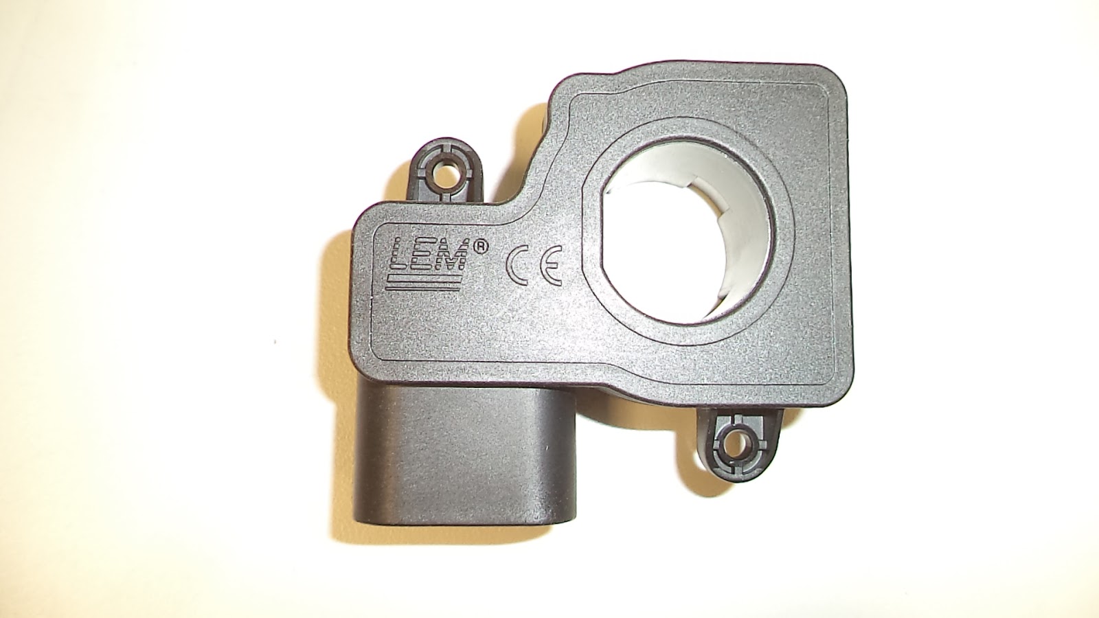
DSC05609 top view of 400 amp current sensor.  As shown above, the power cable opening is 21.57 mm ID left to right, and 22.62 mm ID top to bottom.


DSC05608 of the current sensor showing the internal pins labeled D, C, B , and A.  This current sensor mates to the purple cable socket (part number CWHCURTH-W1559453) shown  below in picture  DSC06316.

The current sensor has the following markings:

LEM
716183093257
>PA66-GF25<


Wiring harnesses that were included in the Orion BMS-48 Controller.


DSC05619 of the multiple wiring harnesses provided. 

The part numbers as printed on the exterior of the plastic bags were sometimes different than the part numbers located internally so both numbers are listed.

(starting at 12:00 - top center ):

CWH126-W1472408, with internal part number CWH126 KSM1915


DSC06308

 
DSC06307

This cable has 12 orange wires labelled 1 to 12 and 1 black wire labeled 1.  Plastic plug is labelled 369.

WHTHEXPO2-W156640, with internal part number of  CWHTHEXP02 KSM5216.


DSC06315


DSC06314

7 wires, with bottom row (as shown):
blue, black, purple, yellow and black.
top row with red, followed by 3 empty plug locations, and finally a red wire.  The first black wire is paired with the first red wire in the lower row.  The plastic plug is labelled 420.  This cable connects to the Orion BMS Thermistor Expansion Module in the far right socket shown in picture DSC05601.

CWHTP-W1574C00, this cable had an internal part number of  CWHTP KSM0817


DSC06304


DSC06305

A pair of wires, orange and brown.  Black cable covering.  8 wire plug using only 2 wires, orange and brown.  The plastic plug is labeled 384.

CWHMIO2-W1546D19 (bottom right of picture DSC05619) had an internal part number of CWHMI02 KSM4716.  The cable package also included 3 x 120 ohm resistors (DSC06334).


DSC06322


DSC06321

Appeared to be 18 wires, but the 2 black wires ( 1 short and 1 long) were actually 3 wires each, both sets covered in black sleeves.  The plastic plug is also labeled 371 and it connects to the right side socket shown in picture DSC05614 above.


DSC06334 of what appears to be 120 ohm resistors.


CWH366-W155550F with an internal part number of CWH366 KSM5116.


DSC06313


DSC06312

A black wire followed by 12 orange wires (labeled 1 to 12), then a black wire followed 12 red wires (labeled 13 to 24) , then a black wire followed by 12 yellow wires (labeled 25 to 36), and finally a black wire.  The black wires are labeled 1, 13, and 25.  The plastic plug is labeled 420.

CWHCURTH-W1559453,  this part had an internal part number of  CWHCURTH-D  KSM5016.


DSC06316

This cable has a white plug, a purple plug, and 4 pairs of black wires.  On the side of the purple plug (which has an external black housing and 4 wires connected to it) is indicated:  DELPHI  11  PBT-GF20.  This purple plug attaches to the current sensor shown in picture DSC05608 and 5609 above.  When the purple plug is viewed as in picture DSC06316 above, the far right is pin A and the far left is pin D.  


The white plug has 12 wires (4 go to the purple plug) and the white plug is labeled 371.

THERM2002-W1573D0B, which appears to have 20 thermocouples with 2 wires each.

CWHTHEX202-W1531B?  (center of picture), this part had an internal part number of HTHEX202  KSM4116. 


DSC06320


DSC06319


DSC06318

top row: black followed by 5 white, then black followed by 5 white.
lower row, identical to upper row.  The plug is labeled 371


DSC05620 of the CANDAPTER CAN bus interface with software