Wednesday, March 29, 2017

Installation of a Bendak HD-9 Four Post Lift

A BendPak HD-9, 9000 pound capacity commercial grade four-post lift (serial number 9966-001-012) was purchased from Autobodytoolmart in Elgin, Illinois ( http://www.autobodytoolmart.com/  ,  800-382-1200 ).  Like the Rolling Bridge Jack (previous posting dated 3/25/2017), the shipping was free and it was shipped direct from BendPak in Santa Paula, California.  The shipping weight was 1686 pounds.

BendPak HD-9 Specifications:
  • Lifting Capacity: 9,000 lbs. / 4,082 kg
  • Overall Width: 110-1/4" / 2,800mm
  • Outside Length: 174" /4,420mm
  • Overall Length: 200" /5,080mm
  • Height of Columns: 88" /2,235mm
  • Runway Min. Height: 4-1/2" /114mm
  • Max Rise: 70" / 1,778 mm
  • Max Lifting Height: 74-1/2" /1,892mm
  • Width Between Posts: 100-1/4" /2,555mm
  • Runway width: 19" / 483mm
  • Width Between Runways: 37-1/2" - 44-3/8" / 952 - 1,127 mm
  • Length of Runways: 164" / 4.166 mm
  • Min. Wheelbase @ Rated Capacity: 115" /2,921mm
  • Min. Wheelbase @ 75% Capacity: 100" /2,540mm
  • Min. Wheelbase @ 50% Capacity: 85" /2,159mm
  • Min. Wheelbase @ 25% Capacity: 70" /1,778mm
  • Locking Positions: 12
  • Lock Spacing: every 4" /102mm
  • Lifting Time: 45 sec.
  • Motor: 220 VAC / 60 Hz / 1 Ph
  • ABTM part number: 7990
Note: An air supply (minimum: 30 psi / 3 CFM) is required for the safety-lock mechanisms to disengage. It is solely the responsibility of the end-user to provide, install and maintain the air supply.

The manual (HD-9 version L) as supplied provided most of the necessary information for the building of the lift.  To increase confidence, and prior to building the lift, several youtube videos of lift installations were reviewed to see how others had attacked the project. 

https://www.youtube.com/watch?v=4SHgSLauUaM&list=PLZU3rdralvGMKEjYOm-VvGhd1AcydgvXV 

https://www.youtube.com/watch?v=leYgoqd2i5c&t=212s 

Interestingly the videos show very few close up pictures of the details of the construction.  The purpose of this posting is to supplement the manual and the youtube videos so that others who may elect to build their first HD-9 lift might be able to save some of the time that I wasted in my first build.

The lift was supplied tightly packed within disposable angle iron end frames as a long rectangle (DSC05593).  A forklift was required to unload the 1686 pound shipment.


DSC05593 of the packed lift after removal of the parts boxes that were stacked on top and removal of the cardboard protective coverings.


DSC05625 of the HD-9 lift label serial number 9966-001-012.


DSC05633 Each cross member has 4 black plastic slide blocks mounted to pairs of pins on each side.  A mallet was initially used for placement, but some of the blocks did not fully seat, so a "C" clamp was used to squeeze the plastic blocks (DSC05634) closer to the cross beam.  Once the bottoms of the plastic blocks were lowered into the column, the "C" clamp was removed, and the crosstube then slid smoothly down the column. 


DSC05634 showing the use of "C" clamps for compression of the black plastic slide blocks so that they fit into the column.

When a forklift is not available, some youtube videos show pairs of posts positioned horizontally on the floor (  https://www.youtube.com/watch?v=0EsW7llK5IA )  , and then two workers insert the crosstube at the top of the masts while still at floor level.  The crosstube is then pushed toward the base of the column, and finally both columns (now connected with the crosstube) are lifted up to a vertical position.  In this blog build a forklift was available, so pairs of the columns were instead positioned on the concrete floor and the crosstubes were lifted and then lowered into the columns.  It was also elected to place a pair of empty 55 gallon steel drums under each crosstube next to the columns to maintain a comfortable working height.


DSC05636 showing the use of an empty 55 gallon steel drum to support the pieces during assembly.  The Powerside Runway is the length that has the hydraulic ram attached to the underside and it is located next to the hydraulic drive.

The drums created a comfortable working height for access to the underside of the Runway.  The second runway is described as the Offside Runway.  The HD-9 allows the Offside Runway to be positioned for either narrow or wide cars.  The BMW under construction has an outer wheel edge to edge distance of about 65 inches so the Offside Runway was located at its furthest point from the Powerside Runway.


DSC05641 Initially only 2 drums were used to support the lift during construction.  While the safety ladders ( "ladders" ) were installed on the Powerside, without thinking "fully", the Offside Runway was then dropped onto the crosstubes before installing the corresponding offside ladders !  Well, the crosspiece ends close to the forklift descended to the bottom of the columns and the whole lift tilted to the side.  Ugh.  The fork lift was then used to raise the right side back up, 2 more drums added for support, and then the offside safety "ladders" were installed to lock the crosstubes in place.

The Installation and Operation Manual describes "Large Windows" and "Small Windows" in the crosstubes.  These openings allow space for partial insertion of the pulleys that are attached to the Powerside Runway.  The words Small and Large relate to the height of the openings.  The "Large Widows" are in the cross beam that is farthest from the power hydraulic unit and their size allows for two pairs of pulleys (DSC05681). The "Small Windows" are the openings located in the crossbeam adjacent to the power unit and they only have enough height for two single pulleys (DSC05683).  It was found to be challenging to install the double pair of pulleys.  It was elected to tilt both columns and the crosstube about 20 degrees away from the runway and then "shoehorn" the pulleys into the crostubes.  If the manufacturer had made the height of the windows about 1/4" more, it would have been much easier to install the runway. 
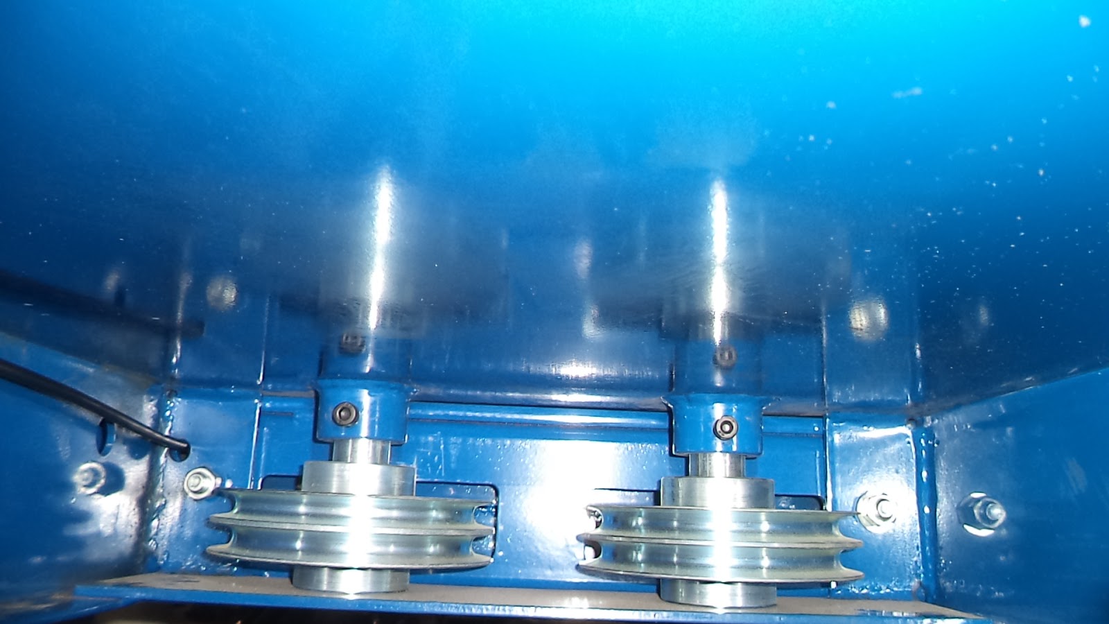

DSC05681 showing the "Large Windows" with the pulleys installed at the far end away from the hydraulic unit.  The pulley shafts are retained by the black hex bolts at the top.


DSC05720 after removal of the black hex bolts and the pulley shaft.  Picture shows how the shaft is retained by the hex bolt.


DSC058721 showing the incorrect placement of the cable above the corner bolt.  When it was hard to feed the cable around the corner bolts it was easier to just remove the corner bolt, push the cable downward, and then reinstall the bolt.  This "Large Window" opening is about 1.75".


DSC05722 showing the correct location of the cable below the corner bolt.


DSC05683 showing the left side "Small Window" that is adjacent to the hydraulic unit and is about 1.25" in height.

Extra Parts !!

Then, at the end of the "build", as always it seems, there were some extra parts that somehow were overlooked during construction.  After considerable further study, it was decided to send pictures of the parts to the technical service department at BendPak.  A teleconference with Abraham quickly determined where the parts belonged.   


DSC05642 picture of the four sets of "extra" M10 x 450 mm bolts with nylon insert nuts and Aluminum spacers (cylinders) that have a 1.125" diameter and are 0.625' thick.


The picture above was supplied by Abraham at BendPak Technical Support (800-253-2363, ext. 196) to show the proper placement of the bushings shown in DSC05642  .  Note that the bottom edge of the safety ladder (on the left side wall) is clearly above the base plate.


DSC05646 of the "extra" lubricating grease nipples (appears to be Zerk fittings).  The fittings were eventually installed using an 8 mm nut driver at the locations shown in pictures DSC05677 and DSC05673 below.  A call to the factory confirmed that the pressure fitting (right side) was intended to be installed on the top of the push button switch as shown in picture DSC05671 below.  It was elected to substitute this fitting with the fittings shown below in picture DSC05741.


DSC05741 of the air line fittings that were purchased separately and used to supply 30 psi compressed air to the push button switch.


DSC05640 showing the use of a small wrench to grab the spring and hook it around the blue retention peg in the cross beam.  This wrench was used to help remove, and then reinstall the springs when needed.
 
 
DSC05680 showing the proper placement of the lifting cable around the small pulley in the crosstube.   The weight of the car and the runways hold the cable under tension and the pulley is pulled outward and held close to the ladder.  If the cable were to break, then the springs attached to the small pulley pull the pulley inward toward the mid line of the lift, and safety pins then lock to the ladder to prevent further downward movement of the lift.


DSC005756  showing the lowering handle (black knob, press to lower) located above the red fill port of the hydraulic reservoir.  As the lift is raised there are a series of loud clicks as pins move up the safety ladders.  When the lift is raised to its required height, this lowering handle is pressed to allow the lift to settle back down until pins in each column engage the safety ladders.  The lift is not considered to be safe for use until the safety pins have locked and the lift no longer descends.


DSC05667 the installation manual (page 25) suggests using 12 quarts 10 WT Hydraulic Fluid or Dexron III ATF.  Three gallons of O'Reilly's Premium ATF Transmission Fluid (part D-1, at $18.99 per gallon) was loaded and interestingly, the reservoir dip tube (located under the red cap) still did not show the reservoir as being full to the top.  


DSC05757 showing the on/off power switch for the hydraulic pump (upper left in picture on black box).  For initial testing the 240 volt plug shown was temporarily installed on the hydraulic unit.


DSC05648 showing correct placement of one of the runway stops. The tabs in the center prevent the yellow stop from falling forward and laying flat on the runway.  There are clips on the end of each Aluminum rod (Tire Stop Pin) to prevent it being dislodged.


DSC05691 showing one of the four Aluminum Tire Stop Pins (top right rod) that are used to secure the front tire stops and the approach ramps.  The retention clips are described as 12mm SS Rotor Clips on page 27 (figure 16.1) of the manual.  The clips fit very snugly, and to facilitate installation, a socket wrench socket was selected whose id allowed the rod to insert, but whose OD matched the diameter of the Rotor Clip.  With leather gloves (sharp edges) the socket was then used to force the rotor clips to place. This clip  appears to be similar to a DTX-12 Shaft Ring found here https://www.rotorclip.com/cat_pdfs/dtx.pdf  .

Hydraulic unit


DSC05638 When working alone, it was convenient to use a car jack to elevate the hydraulic unit while the four mounting bolts were installed.  A second helper at this point would have made the process much easier.

 
DSC05690 of the fitting used to connect the right front opening on the hydraulic unit to the hydraulic hose.


DSC05645 of the end of the heavy duty hydraulic line with the 90' elbow.  The hydraulic hose then passes through a plastic Flex Hose connected to the powerside runway and it then travels alongside the cylinder before the hydraulic hose's straight end terminates into a 90 degree brass fitting that is attached to the hydraulic cylinder (picture DSC05685).


DSC05685 showing the hydraulic hose (with straight end) connected to the ram end of the cylinder after a 90' fitting (NPT to hydraulic) was installed on the cylinder.


DSC05671 the brass 90' (NPT to air hose) at the picture bottom center (back left side of the drive unit)  is connected to the base end of the ram (picture DSC05668) with plastic tubing.  This is the hydraulic return line for the ram.  The bottom of the push button at the top left in the picture terminates at each of the 4 posts after passing to the tee shown in picture DSC05669.  Note that the inlet (top) of the push button switch has the brass fitting previously shown in the picture DSC05646 above.


DSC05668 showing the termination point of the hydraulic return line from the drive unit at the base of the ram cylinder.  This hydraulic return line terminated at the left base of the hydraulic unit as shown in picture DSC05671.

Air Actuated Safety Locks

The lift requires a 30 psi air supply to actuate the safety locks located on each column.  When air pressure is applied by pressing the auxiliary push button, the air cylinders withdraw the latches on each safety ladder with a prominent click from each ladder.  If one then presses the lowering handle (picture DSC05756 above) on the hydraulic drive, the hydraulic fluid within the cylinder then returns to the plastic reservoir located under the hydraulic pump.
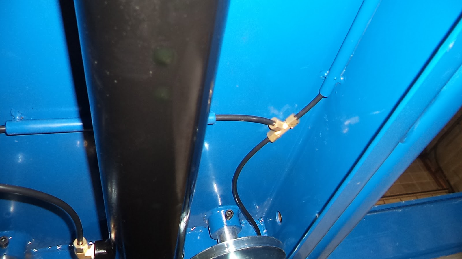

DSC05669 showing the brass tee (right center) where the air line from the bottom of the push button switch terminates.  The other black plastic lines from the tee then pass front and back to the cross beams and then branch again to each post.  The push button switch along with these air lines direct 30 psi air to a pneumatic piston located in the cross bar by each column (picture DSC05672).  When activated, the pneumatic piston disengages the safety locks from the safety ladder with a loud click. 


DSC05672 showing the termination of the compressed air line into one of the four pneumatic pistons located adjacent to each cross beam.  When pressurized, the action arm disengages the safety pin from the ladder, and if the lowering handle on the hydraulic pump is pushed downward, the hydraulic fluid returns to the reservoir and the lift begins to lower to the ground.


DSC05676 Each pulley shaft has a threaded opening at the bottom.  The white pointer indicates where the opening can be found and a close up view is shown in DSC05677.


DSC05677 showing the underside of one of the four pulley shafts located on the powerside runway.   An 8 mm nut driver was used for the installation of the Zerk style lubrication fittings. 


DSC05673 At the center of the picture can be seen the pulley shaft (with the large E clip ring) into which the Zerk fitting has been installed.  Each cross tube has two Zerk fittings.

Floor Mounting

The factory supplies 16 anchors (DSC05710) that are mounted after drilling 3/4" holes approximately 4.5" deep into the concrete floor with a masonry hammer drill.   The anchors result in sixteen 3/4" x 2.25" studs protruding from the floor.  If it is necessary to relocate the lift to allow movement of other equipment within the facility, the protruding studs would present a problem. 


DSC05710 of the factory supplied floor anchors.  The anchors result in permanent 2.25' x 3/4" studs protruding from the floor in 16 locations.

Alternatively, it was decided to instead use floor anchors (DSC05711) that mount flush to the floor.  The baseplate of the lift is then secured using 3/4" x 3" bolts.  By using this alternative design, it is possible to remove the bolts, relocate the lift, and still have full access to the floor area without damage to the forklift tires.


DSC05711 of the alternative floor anchor system that allows for the movement of the lift within the facility without the inconvenience of protruding studs that might interfere with rigging or cause forklift tire damage.

Edited 7/22/2018


DSC06372 Showing one of the 87.125" tall posts prior to placement of floor anchors.  The channel opening is the inside face of the post.  The post is 6" x 5" tubular steel and the floor mounting plate is 10" (width of the lift) x 12" (length of the lift) x 0.375". 


DSC06373 Showing the outside edge and face of the post.  The mounting holes are 1" diameter and they are 8" (width of lift) and 10" (length of lift) center to center.


In the following youtube video the HD-9 lift can be seen  ( https://www.youtube.com/watch?v=RoUoSKoIb14  )  being moved using the optional BendPak castor kit (  http://www.bendpak.com/car-lifts/accessories/caster-kit.aspx  ). 
Another video reviews the castor kit.   https://www.youtube.com/watch?v=M0QLkzzRDCA 

Peter B. and I built the BendPak HD-9 Four Post Lift unit over three Saturdays.  With what was learned by this build experience the next installation  (also using two people and one forklift) should only require 2 Saturdays to complete.

Saturday, March 25, 2017

BendPak RJ-45 Rolling Bridge Jack

A BendPak RJ-45 Rolling Bridge jack (serial number 11126-002-002) was purchased from Autobodytoolmart in Elgin, Illinois ( http://www.autobodytoolmart.com/  ,  800-382-1200 ).  Like the 4 post lift, shipping was free and the jack was shipped direct from BendPak in Santa Paula, California.  The shipping weight was 455 pounds.

This jack will allow for the elevation of either end of the EV for brake or suspension work.


DSC05659 showing the Bridge Jack on a dolly prior to installation on the four post lift.  When the bridge lift is placed directly on the ground the rollers do not contact.  When no silver cylindrical spacers are used between the lifting arms and the rubber pads, the top of the rubber pads is about 20.5 cm above the ground.  This picture above shows the use of the pair of 2.75" spacers.


DSC05743 of the two pairs of factory provided spacers.  When stacked, the 2.75" and 5.5" spacers can provide an additional 8.25" of lift.


DSC05661 of one of the pair of utility rail channels that are located on the inner side of  both runways.


DSC05664 showing one of the rollers (located at each corner of the bridge jack) that allows for movement of the jack front to back on the lift.

Installation of the safety brackets required more thought than was expected.  If the supplied M10 x 25 bolts are inserted from the mid line outward toward the rails, then they are too long (DSC05726).


DSC05726  showing the excess length of the bolts when installed from the mid line.  For the purpose of the photo, the bracket has been reversed for better visibility.  When the bracket is properly placed the pair of large access holes (for tightening) are toward the viewer, and to the left.

Alternatively, if instead M10 x 20 bolts were used, the process of holding the corresponding nuts on the rail side through the access holes would be difficult.   The solution was to place a table below the bridge jack and lower the lift until the bridge separated from the rails and the rollers were elevated above the rails (DSC05730). 


DSC05730 showing the rollers elevated above the rails.

It was then possible to insert the supplied M10 x 25 bolts from the outside toward the mid line (DSC05732).  An ideal solution since it provided maximum separation between the bolt heads and the rails, and the bolts can not be displaced once installed.


DSC05732  of the M10 x 25 bolts after being inserted.  Note the space between the bolt heads and the blue rail.

When attaching the bracket and tightening the bolts, a spacer (thin flat file) was placed between the bottom of the rail (blue) and the bracket (black) to maintain a uniform distance.  It was also necessary to slightly elongate the factory drilled hole on one of the brackets to provide enough clearance so that the bracket would not scrape the rail when the lift is moved.


DSC05736  of the installed safety bracket on the underside of the utility rail.  The bracket prevents the jack from "jumping" off the rail when being moved.  The photo also shows the placement of a backing wrench for use when tightening the bolts.

The operator manual suggests using a hydraulic fluid equivalent to Mobil DTE 13M.  An oil from McMaster Carr was selected that is described as Mobil DTE 24 Mineral Base Oil with ISO 32 and SAE 10W  (cat 2158K11, 1 gallon $25.43).


DSC05744 of the BendPak RJ-45 on the BendPak HD-9 four post lift.

Youtube videos include:

https://www.youtube.com/watch?v=R8i2eZMDQho 

Friday, January 6, 2017

Illuminated 5 Speed Shift Knob


It was found possible to purchase an illuminated "Universal Manual Shift Knob" on eBay for $12.75  delivered price (  !!!  ) from the seller "affordableonly" (  www.icebeamer.com ) .   The eBay compatibility table provided indicated which BMWs might work, but the table only goes back to 1999.  When using the "look up compatibility" function, the inquiry for 1992 is shown to be "not compatible".  This is not accurate as it was confirmed to fit perfectly with both the 1992 325i and 1993 318is that I am converting to EVs.  What makes this device remarkable is that it does not require any wiring changes to the car.  The batteries are part of the knob and simply pressing the shift tab turns on the device.  Going forward it may be desired to remove the batteries and run wires down the side of the shift knob shaft to an ignition switch controlled 5 volt supply.


DSC05401 of the exploded view of the components.  Note that several buttons (left) were provided to allow for different transmission types.  The buttons rest on a clear plastic circle that sits on top of the black control button in the center of the PC board.  Pressing the button activates the light.  The hex wrench sets a screw to secure the knob to the shift knob shaft and the black plastic bushing inserts (center bottom) allow for different shaft diameters.  The body of the knob (far right) is threaded so that the knob face (far left) can be unscrewed for replacement of the batteries.  


Picture DSC05403 showing the top side of the PC board with the three blue LEDs.  The center black rod is the on/blink/off  control button.


DSC05404 showing the bottom of the device where it is powered with two 3V Lithium batteries (type CR2032).  The red insulator prevents contact with the Aluminum body of the shift knob.


DSC05396 showing the shaft that supports the shift knob.  This shaft is solid and 14 mm in diameter.  This diameter is exactly the correct diameter to fit directly into the base of the illuminated shift knob without using any of the plastic inserts that were provided.  To connect an external power source to an illuminated knob might require some machine work, possibly a groove on the side of the shaft, or a hole down the center of the shaft.  Alternatively, some commercial illuminated shift knobs rely upon the leather boot to cover up the wires as they exit from the shift knob base.  Or, if the boot leather does not adequately hide the wires, a piece of black heat shrink PVC tubing might be used over the shaft such that the knob wires pass within the PVC tube.  After shrinking the PVC, the wires would both be firmly held and hidden from view.


DSC05395 of the original shift knob in the BMW 318is.


DSC05397 of substituted shift knob.  The six screws on the knob face can be removed, but they are only decorative.


DSC05400 of knob when illuminated.  Very Nice!

Thursday, December 8, 2016

Tesla 5.3 kWh Battery Module Monitoring Board - Part 1

The recent availability of salvaged Tesla battery packs has led to efforts to repurpose them for solar applications (see reference at end below) and it might be possible to use them in this BMW 325i EV conversion project as well.   The primary concerns with using salvaged Lithium ion batteries include the condition of the batteries when received, and the additional requirement of safe handling when later charging and discharging the batteries after installation.  For safety, either the purchase or the development of a battery monitoring system capable of controlling 6 or more of the Tesla modules, each containing essentially 6 batteries (36 total) is a must.  For purpose of better understanding and possible reverse engineering of the Tesla battery control board, a monitoring board was purchased from K-Ash on Ebay.  (Picture DSC05118)


Picture DSC05118 of the component side of the Tesla battery control board.  There is one of these boards located on each battery module.

The board as received was copyright 2012, and it is labeled PCAB (1020796).  It has a white sticker labeled 1021749-00-REV 03 and 0314C60002094.  The board is designed to monitor the 6 cell groups contained in each module. 

The black 16 pin chip (U4) on the upper left of the board is an SI8642 and it is an isolator chip to separate high voltage from ground.  http://www.silabs.com/Support%20Documents/TechnicalDocs/Si864x.pdf

The black 64 pin chip (U1) in the lower center (largest chip) of the board is a Texas Instruments TI BQ76PL536A battery monitoring chip.  http://www.ti.com/lit/ds/symlink/bq76pl536a-q1.pdf

The C8051F536 microprocessor (U100) that controls the board is immediately to the left (and slightly higher) than the 64 pin battery monitor chip (U1).   http://www.silabs.com/Support%20Documents/TechnicalDocs/c8051f52x-f53x.pdf 


 Picture DSC05126 showing the  three connectors used on the reversed side of the Tesla battery control board.

The long 15 pin white connector (J3) is a JST S15B-PASK-2 (the mate to this connector is JST PAP-15V-S and it uses SPHD-001T-P0.5 crimp pins).  It is labeled as Cell 6, 4, 2, 0, 1, 3, 5, with every other pin left unconnected for further voltage isolation.   The cable that attaches to this connector is terminated at six different locations on the battery pack.  

The large black 10 pin connector (J1) is a Molex Mini-Fit Jr Series 5569 and it is available from DigiKey ( http://www.digikey.com/product-detail/en/molex-llc/0015978102/0015978102-ND/3157084 ). 

The corresponding mate to J1 can be purchased here:  http://www.digikey.com/product-detail/en/molex-connector-corporation/15-97-5101/WM4772-ND/1624637

The small white connector (J6) is a JST S4B-PASK-2 and the mate is JST PAP-4V-S.  The pins are labeled TS1+, TS2+, TS2-, TS1-.  These are the thermistor leads (Temperature Sensor).

The Tesla PC board is fastened to the module housing with four black attachment pins.


Picture DSC05236 showing one of the mounting points with the inserted attachment pins.  Using a pair of needle nose pliers the small center pin can be pulled out (DSC05237).


Picture DSC05237, once the pins are fully removed, the remaining black piece pulls smoothly away from the battery module's plastic frame.  


Picture DSC05127 showing the dimensions of the Tesla battery control board.  These dimensions can be used to fabricate a proto board that can be directly attached to the existing 5.3 kWh Tesla battery module. 
--------------------------
UPDATED 12-31-2016
Error: the 102.5 noted as the horizontal distance between the left and right mounting points in the picture above is actually 92.5 mm.


Picture DSC05357 showing that the BMS side of the board actually has a total of six mounting points that may be used when fabricating a replacement printed circuit board.  The left four were described above, but the right two were discovered upon further examination.  The top row of three mounting points are all 49 mm above the bottom row of three mounting points.  The distance between the far left pair and the center holes is 92.5 mm, and the distance between the center pair and the far right pair is 79 mm.
-------------------------------


Examples of Tesla Modules being used in a Solar Project

An example of a solar project is http/wk057  where an off grid battery system was constructed that used 36 batteries (191.25 kWh) from 2.25 salvaged 85 kWh Tesla cars. ( https://teslamotorsclub.com/tmc/threads/plan-off-grid-solar-with-a-model-s-battery-pack-at-the-heart.34531/ ).  The project also includes an attempt to produce a custom BMS controller as a plug in replacement for the Tesla battery control board.  Some pictures of that project can be found here:   
(  https://teslamotorsclub.com/tmc/threads/in-development-inexpensive-custom-bms-for-tesla-battery-modules.51095/  )


Par 2 of this blog was posted on 2/5/2018?

Wednesday, December 7, 2016

Tesla 5.3 kWh Battery Modules Overview

Six Tesla Model S battery modules, rated 24V, 250Ah, 5.3kWh, and comprised of 444 Panasonic 18650 3400mAh cells, configured 6S74P, were purchased from A-Kash on Ebay.  These batteries will provide the same 144 volt nominal pack voltage as the Yellow tops currently being used, but since they can be discharged more completely, better range will be achieved.  These batteries will initially be monitored using an Orion controller and conveniently, the Orion is directly compatible with the Eltek 67.115.0 charger already being used and described in this blog's May 15, 2016 posting.

Comparison of 6 Tesla Batteries Versus 12 Yellow Top Batteries

The total pack voltage is approximately the same at 144 volts.
Weight of the 6 Tesla batteries is about 330 pounds compared to 717.6 pounds for the 12 Yellow Top 8050-160-FFP-D31T batteries.
The 6 Tesla batteries should provide 31.8 kWh and it is anticipated that about 80% of the contained energy will be available for use.  The 12 Yellow Tops provide about 10.8 kWh of which about 50% of the contained energy is expected to be available.  It is estimated that this 1992 325i EV conversion requires about 400 watt-h for each mile travelled, then the Tesla batteries should allow for a range of about 63.6 miles compared to the Yellow Tops expected range of 13.5 miles.

Upon arrival the modules measured between 23.09 and 23.12 volts. These batteries were extracted from a 2015 Tesla Model S (vin 5YJSA4H29FFP74017)  which originally used a 85 kWh pack.  The VIN can be decoded here: https://teslamotorsclub.com/tmc/threads/decoding-tesla-model-s-vins.7638/

Each battery module is labeled with a sticker that indicates both a part number and a serial number.  All of the batteries received were part number (P) TPN 1009312-00-E.  The following serial numbers and corresponding module voltages were recorded:

Tesla Batteries Ability to Hold Charge

                                         12/7/2016           1/29/18                              1/26/19                             5/25/20
(S) TSN T14G824536     23.09 volts          23.07 volts    (-0.09%)       23.03 volts   (-0.17%)    22.86 volts   (-0.74%)
(S) TSN T14G824283     23.11 volts          22.29 volts * (-3.55%)       21.74 volts * (-2.47%)   21.60 volts*  (-0.64%
(S) TSN T14G824610     23.11 volts          23.10 volts    (-0.04%)       23.07 volts    (-0.13%)   23.07 volts    (0.00%)
(S) TSN T14G824617     23.12 volts          23.08 volts    (-0.17%)       23.03 volts    (-.022%)   22.81 volts    (-0.96%)
(S) TSN T14G824692     23.12 volts          23.09 volts    (-0.13%)       23.06 volts    (-0.13%)   23.05 volts    (-0.04%)
(S) TSN T14G824708     23.12 volts          22.30 volts *  (-3.55%)      21.76 volts *  (-2.42%)  21.72 volts*  (-0.18%)
Updated 1/29/18;  1/26/19;  5/25/20 
                                  6/14/2021    compared to voltage on 12/7/2016
(S) TSN T14G824536     22.7 volts    (-0.39 volts, or -1.69% from 12/7/2016)
(S) TSN T14G824283     15.6 volts *  ouch
(S) TSN T14G824610     22.8 volt      (-0.31 volts, or -1.34% since 12/7/2016)
(S) TSN T14G824617     22.5 volts     (-0.62 volts, or -2.68% since 12/7/2016)
(S) TSN T14G824692     22.8 volts     (-0.32 volts, or -1.38% since 12/7/2016)
(S) TSN T14G824708     21.5 volts *        
Updated 6/14/21 

Note that over the period of 12/7/16 to 5/25/20 (1265 days) the average loss in voltage for the six batteries amounted -2.567% per battery over a 1265 day (3.518 years) period.  This is a loss of about 0.73% of the original voltage level per year.

Updated  5/25/20, 6/14/21 

If we ignore the two batteries that were damaged, the average voltage of the remaining 4 batteries is 22.7 volts.  The average voltage of the same four batteries on 12/7/2016 was 23.11 volts.  This represents an average change of -0.41 volts (-1.77%) over a 1650 day period (4.521 years).  
Updated 6/14/21 
  
*  These two batteries were installed in the battery box and briefly shorted with a socket wrench (blog entry 6/18/17, picture DSC05985).  The other four batteries have never had a load placed on them.  Note that the voltages suggest essentially no leakage during 13 months of storage.

This will probably be the end of the long term stability test for the batteries and the installation of the Orion BMS will now begin.

Updated 5/25/2020


Picture DSC05178.  After removing the orange rubber terminal protectors on the left, this module (serial # 4610) was found to be partially charged and 23.11 volts. The terminal landing areas (Picture DSC05298  ) under the orange plugs are 37 mm x 37 mm with a M8 x 27 mm center bolt.


Picture DSC05298 of the low voltage terminal (left side when viewed from the top) after removal of the orange cover.

Updated 5/13/18

Picture DSC05176.  Each battery module has a BMS control PC board located at one end.  The yellow tape (one at the left and two at right)  secure the top and bottom plastic vacuform type covers to the module.  The tape appears to be a Polyamideimide tape (likely Kapton, see https://www.uline.com/BL_6407/Kapton-Tape?pricode=WE491&AdKeyword=kapton%20tape&AdMatchtype=e&gclid=CPWO2_v4y9ACFZA2aQod4YMFgQ&gclsrc=aw.ds  )


Picture DSC05191 After removal of the four black mounting pins the control board can be pulled away from the module to reveal a pair of white connectors.  The white left 15 pin connector is used to measure the voltage of six battery subgroups of cells.  The right connector  with pairs of blue and yellow wires are connected to temperature probes.  The white connectors can each be removed by first pressing the top center tab (corrected 4/28/17) and gently prying upward while pulling on the connector.  The Gold surfaces at the top of the picture are the tape covered bent ends of the module's heating/cooling coils.


Picture DSC05196  showing the four wires that travel on the top of the pack (black, red, yellow, and blue) and the three wires on the bottom of the module (green, blown and orange).  Each of the wires is connected to a different region of the battery surface (Picture DSC05186) and provide different voltage measurements (see below).


Picture DSC05186 showing one of the wires that is welded to a region of the metal face plate.


Picture DSC05192 showing a close up of the right side temperature sensor (TS) which is connected to the BMS board with a pair of blue wires.  The left side (yellow wires) temperature sensor measured 13.74 k ohms and the blue sensor wires measured 13.79 k ohms.


Picture DSC05195 showing the measurement wires that are terminated (welded, picture DSC05186 above) to different regions on the face of the battery module.  The silver surfaces appear to be contiguous, but actually they are cut to provide four separate regions on one side of the battery and three separate regions on the reverse side.

A Klein Tools CL2000 digital Voltmeter was used for all measurements.  The CL2000 can measure up to 1000 volts DC and up to 400 amps DC.   The following voltages were measured from Left Terminal (when viewed from the top with the bms board close to the viewer ) of a battery (serial # 4610) to each of the sensor wires:

Cell 6 - blue    -   23.10  volts
Cell 4 - yellow -   15.40  volts
Cell 2 - red      -     7.70   volts
Cell 0 - black   -     0.00   volts
Cell 1 - brown -     3.86   volts
Cell 3 - orange -   11.55   volts
Cell 5 - green   -    19.26   volts

Voltage between Left Terminal  (-) to Right Terminal  (+) = 23.1 volts

Updated 1/29/18
Updated 5/13/18

The pack is considered to be 0% State of Charge (SOC) when the module measures 18.6 volts.  A 70% charge typically measures 23.1 volts, and a 100% charge is about 24.9 volts.


DSC05180 showing the side of the module opposite to the electrical control side.  Each coolant line was shipped sealed with black caps to prevent residual coolant from leaking out during shipment. The three gold regions are the Kapton covered u-bends of the serpentine cooling tubes that make 8 lengthwise passes through the battery pack.  Note that the vertical positions of the nipples are different.  The left side (input) is lower than the right side (output).  


Picture DSC05232 showing a close up of  the 5/16" coolant nipple after the black cap was removed.   

The cooling loop uses a pair of 5/16" (ID) tubing nipples that appeared to a Dorman 800-080 or 800-120 type Fuel Line Quick Connector.  Although these connectors were tested both bottomed out when installed and neither snapped tight as anticipated.  Although one can probably install straight tubing with hose clamps, we are still looking to source the correct couplings.
Details of Dorman connectors can be found here:  http://www.dormanproducts.com/gsearch.aspx?type=keyword&origin=keyword&q=fuel+line+connector  .  These connectors can also be purchased (Dorman, ebay.com and Amazon.com) and they are available for different tubing sizes, as straight, 45 degree and 90 degree angled fittings.

------------------
UPDATED 12-19-2016

It was found that Dorman 800-116 Fuel Line Connectors (Summit Racing, part RNB-800-116, at $7.97 per pair) appear to work very well.  These fittings are described as 5/16" Steel to 5/16" (8 mm) Nylon Straight and the connectors  snap on tightly yet can still be removed easily by pressing the tab located on the side.


Picture DSC05324 of the Dorman 800-116 connector after one was snapped onto the Tesla battery cooling fitting.  Some pale blue coolant fluid spilled out during the effort.


Picture DSC05325 close up of both sides of the fitting.  Release tab is evident on left side of the bottom fitting.


Picture DSC05327 of the blue colored fluid that was recovered from the module.   In one of Tesla's battery patents ( http://www.google.com/patents/US20140178722  ) this fluid is described only as " water or another coolant, such as any conventional anti-freeze mixed with water, oil, or even cold air ".   The blue color suggests that the fluid is Propylene glycol, but time permitting, this fluid will later be tested for both concentration and identity.

---------------------


Picture DSC05287:  Each Tesla battery module has a "fin" on each side which extends the majority of the length of the module.  When looking at the modules from the battery terminal end, the right side "fin" has a maximum width of 0.5" (top unit, the rounded section with 7/32" holes) and the remainder of the "fin" is 5/16".  The left side "fin" has a width of  0.375" (bottom unit).  These fins will be used to support the modules in a Mounting Frame that is being constructed that will support 4 batteries.  The Mounting Frame will then be isolated within a Stainless Steel battery box, and the battery box finally placed within the trunk located wheel well of the 325i.   


Picture DSC05230  showing close up of the rear portion of the left hand rail (or "fin") that is 0.375" wide and 0.125" thick.