Monday, October 27, 2014

SRS (Supplemental Restraint System) Sensor dissection


In the previous June 7, 2014 posting, the SRS (Supplemental Restraint Sensor) was relocated away from an area where body repair welding was planned.  Previous research of the literature implied that, if the sensor were to be shocked while powered by 12 volts, then the sensor might act like a fuse at the same time that the airbags deployed.  This suggested that it might be a one time, one use device, and it was wondered how the sensor actually functioned.  Subsequent dissection indicated that the sensor is not a one use device, and what was meant by the literature was only that if powered with 12 volts while being connected to the car and then shocked, that the obvious result would be that the airbags would deploy and thus the airbag would require full replacement !
 
To learn more about the sensors, some were obtained from the body of a salvaged 09/91 BMW 535i.  There are two sensors located under the hood, one on the drivers side and one on the passenger side directly over the wheel wells.  Each sensor  is connected to a wiring harness by way of a 3 wire weather tight plastic plug (Picture DSC01853).
 
 
Picture DSC01853 of the 3 wire weather tight connector.


Picture DSC01854 of the sensor after removal from the 535i.  Note the black O-ring on the male portion of the plug.  Very firm force was required to separate the plug.


Picture DSC01858 after the removal of the orange plastic coating and internal black "epoxy".  A heat gun was used to soften the plastic and epoxy to aid in its removal.


Picture DSC01863 showing the top view of the internal device after cutting open the protective steel housing.  The sensor is a plastic tube (center of the device) that is wrapped in a thin layer of spring steel.  As the sensor is rolled from the right to the left (what would be the front of the car), electrical contact is made between the silver spring steel, and a pair of small copper electrodes that can be seen in the center of the black circle in the middle of the device.


Picture DSC01867 demonstrating the cylinder shaped detector mechanism while at rest.


Picture DSC01866 of the side view of the sensor when rolled to the left and fully deflected (what would be toward the front of the car) during a simulated crash or impact.


Picture DSC01865 showing a second view of the cylinder shaped mechanism when fully deflected (what would be toward the front of the car) during a simulated crash or impact.  In this position the silver spring steel is shorted to the small copper electrodes that are now beneath the spring steel.  When released, the tube immediately snaps back and to the right.


Monday, September 22, 2014

Electric Vehicle Promotion


Some have suggested that a electric conversion car should be in "good taste" and not have obtrusive markings that indicate that it is 100% Electric Drive.  This view is flawed in that part of the point of  building an EV conversion is to show as many people as possible that all electric cars are real, and that there is one driving next to them in traffic.  Having said that, the conversion should be done thoughtfully and the car made as reliable as is possible since it does no good to be seen at the side of the road waiting for a tow truck!

Janusz, at Daxam in Elk Grove Village, is a specialist in the manufacture and installation of vehicle decals and graphics.  With his help, colors were selected that closely matched the 1992 BMW Alpine White and the characteristic blue used by BMW.  Samples decals were initially produced using both a "BMW Blue" style and a lighter "Tiffany Blue" style to see how they would appear. 


Scanned Proof: Electric Logo 2 showing the proofs of the proposed car decals that announce the electric car.  The darker blue does not scan very well in the above picture and the actual decal is very close to the blue that is used by BMW.

 Subsequently it was decided not to waste the original decals, and instead have Daxam produce the "ELECTRIC" logo on a removable magnetic backing using a blue similar to the classic "BMW Blue" on a white that is similar to BMW's Alpine White.  A pair of these magnetic signs were applied to both front doors.  Ready to dance!


Picture DSC01793  of the final magnetic sign ready to be applied to the front door panels.


Picture DSC01792 showing the preliminary installation of the magnetic signs to the door of the 1992 BMW 325i.  The dimensions of the sign are 41" x 6.5" and the sign exactly fits within the lower panel of the door.  This magnetic sign will be removed when the car is repainted at the end of the conversion process and the final decals installed at that time.  In the mean time the magnetic signs will provide visibility during the initial road tests.

Saturday, September 20, 2014

1992 BMW 325i Getrag Manual Transmission Fluid Replacement

To prepare the EV for its initial road test now requires some housekeeping.  Previous tests of the drive train took place with the wheels elevated off the floor without any significant load on the gearbox.  Following the directions found in the Bentley BMW 3 Series Service Manual (section 230), the fill plug on the right side of the transmission was removed (picture DSC01701) and a flexible tubing was inserted.  Using a Performance Tool Quart and Gallon Fluid Pump  (O'Reilly Auto, $9.99), transmission fluid (purchased form Patrick BMW in Schaumburg, Illinois) was pumped into the opening until the fluid level just began to overflow the fill hole.  This process was very efficient.


DSC01701 showing the fill plug on the right side (middle) of the Getrag transmission. 


DSC01702 showing the Performance Tool Quart and Gallon Fluid Pump as it was used to pump transmission fluid into fill hole on the right side of the Getrag transmission.

Sunday, September 14, 2014

Warp 11 End Cap Bolts Upgrade

Tom, a fellow EVer in Pennsylvania who is now converting an 05/1996 BMW 328ti, reported that he observed that his Warp 11, after sitting outside in the driveway this past winter, showed beginning signs of rust on the shaft and the four cap head bolts that secure the Aluminum accessories end cap to the body of the Warp 11.  Although it was anticipated that any shaft that is not oiled or protected will gradually show signs of rust, it was not anticipated that the black oxide coated cap head screws would rapidly rust as well. 


Picture TK09142014-1 showing the shaft and nascent rust on the cap head bolt (center at 12:00).

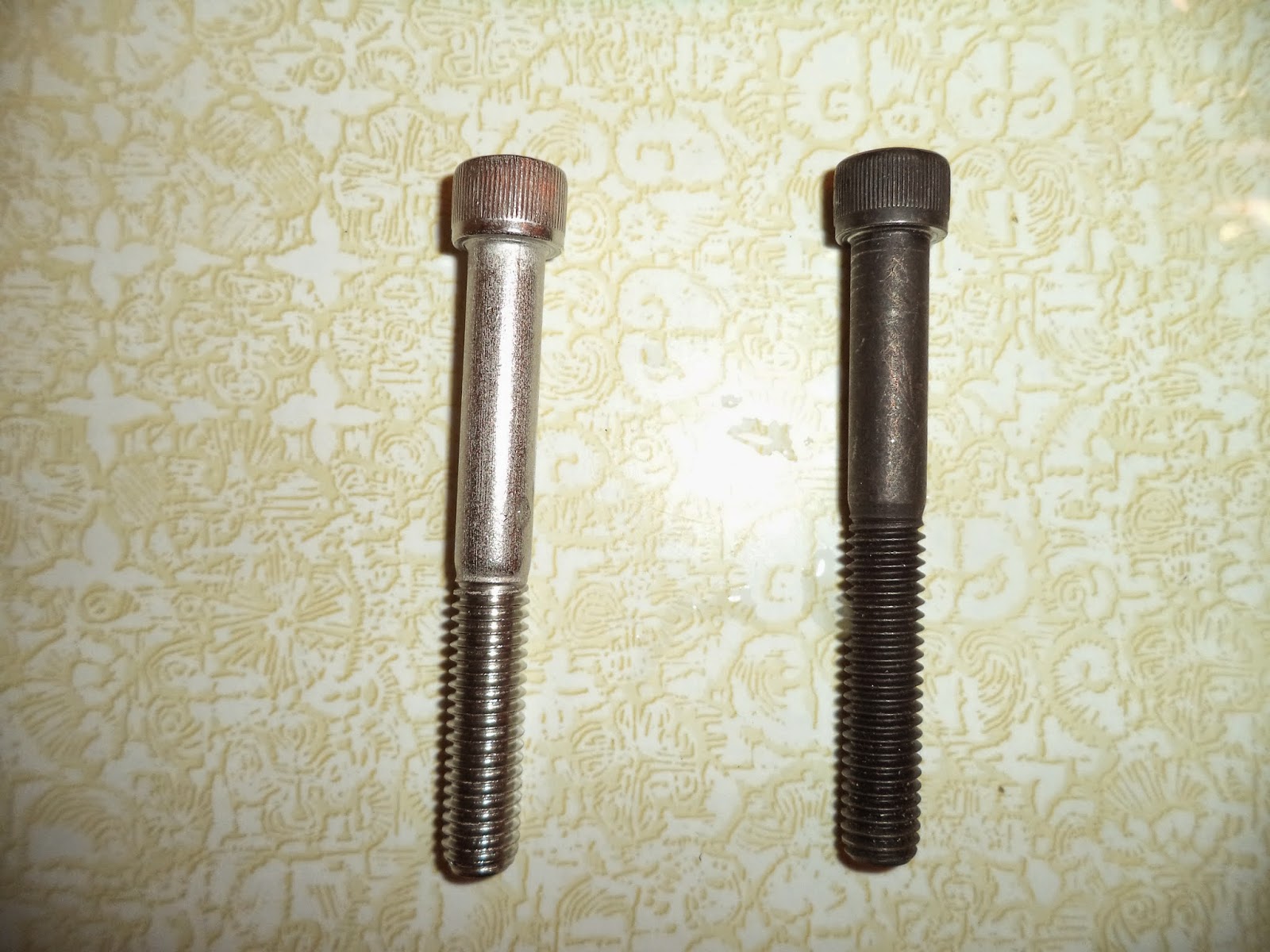
Cosmetics being important, it was elected to preempt the rust and replace the four black oxide steel bolts that are readily accessed at the accessories end of the motor, with equivalent stainless steel cap head bolts.  The bolts were sourced at McMaster Carr (part number 92196A636, $1.04 each, 3/8-16 x 3 inch, partially threaded).  These bolts are Stainless Steel 18-8 (18% Nickel and 8% Chromium) and they are roughly equivalent to a Stainless Steel 303.  They should work very well, and they are not as expensive as the 316 Stainless Steel equivalents (10-14% Nickel and 16-18% Chromium, McMaster Carr part  92185A636) which are priced at $2.79 each!

The bolts were tightened with a 5/16 hex key wrench.

The four equivalently located bolts at the opposite end (transmission side) will not be changed until the adapter plate and transmission are disassembled at some future point.


Picture DSC01708  of the OEM black oxide 38-16 x 3 inch cap head bolts next to the replacement stainless steel cap head bolts.


DSC01711-B showing the Stainless Steel 18-8 cap head bolts installed in the end cap of the Warp 11.

Monday, September 1, 2014

BMW i3 Test Drive

Having waited impatiently for so long, finally the BMW i3 has arrived at Patrick BMW in Schaumburg, Illinois.  The car is amazing to experience and the cabin appointments for the $43k version that was test driven are lovely.  The i3 comes with a 22 kWh lithium ion battery pack and it is designed to provide 85% (18.8 kWh) of rated capacity for 70 miles of range.  The full recharge requires 4 hours at 240 volts.  For an additional $4k, the range can be extended to about 100 miles using a factory installed (front hood area) gasoline powered electric generator that only supplies the battery pack and has no connection to the drive train.

It is interesting to compare the efficiency of the drive unit.  As a regular viewer of the Jack Rickard's weekly electric vehicle conversion webcasts ( http://evtv.me/ ) much technical information has been revealed.  It is generally known that a typical EV conversion requires about 100 watt hours per 1000 pounds car mass per mile.  The 1992 BMW 325i being converted in this blog, weighs in at about 4000 pounds.  It is intended to use 48 CALB 180 amp hours batteries, each at 3.2 volts, to provide a 27.648 kW pack.  (  48x180x3.2=27,648 watts ).  Since the car is about 4000 pounds, about 400 watt hours will be required for each mile driven, thus 27,648/400=69.12 miles of theoretical range.  In fact, one can only use about 85%  of the pack energy, thus a 58.75 mile range is expected.  The current daily commute is about 35 miles each way, so a partial recharge at work will allow the conversion to be a daily commuter.  The i3 on the other hand, has a better range due to its greater efficiency, lighter weight, and BMW's use of Lithium ion batteries instead of the Lithium Iron Phosphate batteries that will be used in this conversion. 

The Tesla, considered by most observers to be the industry standard for performance, if not for price, has a battery efficiency that is "estimated" by Rickard to be about 70 watt hours per 1000 pounds car mass per mile.  The BMW i3 battery pack compares favorably to the Tesla.  By calculation, BMW indicates that the i3 is rated at 27.0 kW-hrs per 100 miles.  Thus, the pack delivers 270 watt-hrs per 1 mile.  Since the car weighs in at 3615 pounds, thus 270/3.615=74.69 watt hours per 1000 pounds per mile.

BMW indicates that they estimate the i3 to have 124 MPGe (miles per gallon equivalent, 137 city and 111 highway) when compared to an "average new vehicle", which is defined as 23 MPG and fuel costs of $11,500 over 5 years.  They assume electric costs to be $0.12 per kW-hr and 15,000 miles of driving per year.  From this data, they calculate fuel savings of $9,000 during the first 5 years, and with tax credits of up to $7,500 , the car becomes an interesting value proposition for those unable to build their own EV.   This car demonstrates what is possible with a 100%  electric drive and it may be possible to incorporate some of its elements into an EV conversion.  Pictures to follow.


Picture DSC01783, this picture speaks for itself.


Picture DSC01751 of the front view of the BMW i3.


Picture DSC01788 showing the traditional BMW kidney shaped "grill" without the aerodynamic drag caused by a functioning actual grill.  No engine to cool, thus no air flow required.


Picture DSC01753 of the passenger side view of the BMW i3 showing the side profile to reduce wind resistance.


Picture DSC01757 showing oblique view of the BMW i3 drivers side.


Picture DSC01760 showing the passenger side coach style doors that are hinged at the outer edges.


Picture DSC01761 showing closer detail of the passenger side back seat door.


Picture DSC01756 of the rear view of the BMW i3.


Picture DSC01768 with the rear hatchback fully open.


Picture DSC01776 with the back seats folded down for full cargo space.


Picture DSC01764 of the driver side control area.


Picture DSC01769 showing the one button start/stop switch and the three position toggle for D/N/R.  The driver "instrument panel" is to the left, and the auxiliary display (navigation, etc.) is to the right.


Picture DSC01754 of the J1772 style charging plug.


Picture DSC01755 of the industry standard J1772 charging socket when the internal illumination is automatically activated.  This illuminated port feature would be a good addition to any conversion project.


Picture DSC01759  of the wall mounted BMW charging station.  Angelo, the very knowledgeable sales consultant that we spoke with at length at Patrick BMW, indicated that BMW and Bosch had partnered up to design and produce  these units. 

Several interesting observations should be noted.  The test drive, which was enthusiastically offered to us by Angelo, was a unique experience.  Although there is a brake pedal, it was really only used at the beginning of the drive when the start/stop was activated, while at stop lights (out of habit) and at the end of the drive when the car was parked.  With constant pressure to the acceleration pedal, the car moves smoothly ahead.  If pressure is taken off of the throttle, then the car immediately begins to gently brake and the car rapidly comes to a smooth stop.  Four of us took the test drive together and our total weight was about 630 pounds.  From a full stop, and shall we say, with a little encouragement, this car is really quick and all of us were pushed back into our seats.  This is exactly what drivers want to be able to feel, and once the public knows what electric cars are capable of, this car should be really popular.  Author's note: To complete the test drive experience, the drive needs to be repeated with only the weight of a single occupant!!

This car is absolutely quiet and it reminded me of the first time I tested the first generation SONY CD player ( http://en.wikipedia.org/wiki/Sony_CDP-101 )  that was offered in 1983 for sale for $1000 at a high fidelity store in downtown Chicago.  With head phones on, when I first tested it, it appeared to be broken since there wasn't any background noise traditionally caused by a phonograph needle or a tape head.  Incorrectly assuming that the unit's volume setting was set too low, I made the mistake of substantially turning up the volume knob.   Let's just say that the subsequent hearing loss was not permanent as I ripped the headphones off as fast as I could once the music began!  The quiet of  this car should help take music to a new level of automobile enjoyment.   

Additional useful information about the BMW i3 can be found here: 

http://en.wikipedia.org/wiki/BMW_i3

www.bmwuse.com/bmwi3

http://www.patrickbmw.com/i3


Monday, July 7, 2014

Installation of the Shift Linkage to the Getrage transmission


All of the initial testing of the Getrag transmission has been conduced without the gear shifter being installed and in the next step of testing it is hoped to fully operate the transmission and shift through all of the gears with the Warp 11 energized.  To achieve this requires the following improvements:  attach the clutch slave to the transmission;  replace the brake/clutch fluids with fresh fluid;  bleed air from the clutch fluid lines;  install the gear shifter and linkages;  and fill the transmission with fresh fluid.  At that point, with the car remaining on four jacks, it should be possible to operate the transmission and run it through all of the gears at different motor speeds.

Previously a backup 5 speed Getrag transmission was purchased on Ebay that was listed as being from a 2002 BMW E46 325i.   Online research suggested that it should be identical to the transmission from a 1992 BMW.  It was decided to maintain the original 1992 transmission, but replace the shifting mechanism and shifter knob with the 2002 parts as they were in better cosmetic condition.  Sadly, after attempting the substitution, it was discovered that the 2002 arms do not fit!  Subsequent careful comparison (which should have been dome prior to initial attempted assembly!) showed the obvious reason why, they are of slightly different lengths, ugh!!


Picture DSC01510 showing the 2002 E46 shifting arm (top) and the 1992 E36 shifting arm (bottom).  Although the transmissions appear to be the same, the shifters are definitely not.  The difference was discovered when it was attempted to install the 2002 assembly into the 1992 car.  Once installed the 2002 shift knob shaft was angled forward and the shift lever bearing was pressing against the rear of the center console opening such that it would not rotate freely.  By comparison, when the 1992 shifting arm was installed, the shifting bearing was centered in the console opening, the shift knob shaft was perpendicular to the floor, and it could be moved freely in any direction..


Picture DSC01514 with the 2002 (top) and the 1992 (bottom) straight selector rods also of different lengths.

Installation of the shifting mechanism proved to be a lengthy project,  but after multiple attempts and a lot of practice, it was learned how to rapidly install or remove all of the components. 


Picture DSC01345 showing the center console still in place, with the rubber shifter covering removed (left center).  The black drive shaft is visible through the circular opening at the right center.  The shifter mechanism passes directly under the circular opening and the shift knob shaft passes up through the round hole, and then the  rubber shifter covering, and finally the gear leather cover (boot).

It was not possible to access the top of the transmission from within the cabin.  The motor mount bolts were removed and the front of  the Warp 11 raised with a floor jack.  The drive shaft center support bearing assembly was disconnected from the car frame to allow the drive shaft to lower significantly away from the console area.


Picture DSC01512 showing the open area created after the drive shaft was lowered away from the console dome.

The challenge is to connect the transmission to both the shifting arm (part 1 in diagram 1) and the straight selector arm (part 9 in diagram 1).

Parts diagram


Diagram 1 is a parts diagram from the RealOem.com website (a phenomenal resource for parts and diagrams) showing an exploded view of all of the Gearbox Shifting Parts.  See:   http://www.realoem.com/bmw/showparts.do?model=CB33&mospid=47498&btnr=25_0013&hg=25&fg=05


Picture DSC01501 demonstrating the shifting arm (center silver) and the straight selector arm (bronze color to the bottom left) both attached to the 2002 Getrag transmission.


Picture DSC01504 showing (view from under the car) the bottom of the console dome and the  original rusted shifter arm bearing being held by a welded bracket on the car frame.  The shifter bearing was removed by inserting a screwdriver between the steel cylinder and the bracket and separating the two parts.  This bearing is a metal tube with a rubber molded insert that slides over the tail section of the shifting arm.  Its purpose is to hold the shifting arm horizontally and allow for slight rotation and slide as the shifter is moved.


Picture DSC01505 after removal of the shifter bearing.  There are two slots on opposite sides of the shifter bearing that allow the metal tabs on the bracket to snap into place.


Picture DSC01507 showing the 1992 shifter bearing on the left and the 2002 bearing on the right. Note that the metal ring is not contiguous and the molded black rubber is visible in the center. This may allow for some compression of the metal cylinder during installation.  The newer shifter bearing was used to replace the rusted one on the left.


Picture DSC01509 end view of the 1992 shifter bearing on the left and the 2002 bearing on the right.  The center opening allows for support of the rear end of the shifting arm as well as permitting both rotational and lateral movements of the arm during the shifting process


Picture DSC01513 after the shifting arm was inserted into the bracket on the top of the Getrag and the retaining bolt (part 3 in Diagram 1 above) was inserted and locked into place.  It was necessary to elevate the tail of the transmission and the drive shaft, as required, to fit the shifting arm and straight selector rod into place.

 
Picture DSC01500 showing the retaining bolt being inserted into the transmission bracket and the shifting arm bushing.


Picture DSC01502 showing the shifting arm installed and locked into place with the 10mm x 40mm retaining bolt (top right) snapped onto the transmission frame.

The most challenging task for the installation turned out to be the pressing of the shifting bearing back into the bracket at the top of the console dome.


Sunday, July 6, 2014

1992 BMW 325i Rear Seat Removal


The ICE initially had its fuel pump and gas tank located under the back seat bottom cushion.  To gain access for servicing, it was necessary to lift the leading edge of the bottom cushion upwards.  The cushion will suddenly pop up and it can then be removed.


Picture DSC01588 showing one of two steel brackets that snap into the bottom of the seat cushion.  This picture is of the passenger side adjacent to the location of the power cables.

To gain access to the rear bulkhead that separates the cabin from the trunk requires the removal of the upper portion of the back seat.  There are two steel brackets that project from the top of the car body at each corner of the back cushion.  There are four openings at the bottom of the rear seat into which corresponding pins on the bottom edge of the back cushion will insert.  Thus, to remove the seat, first pull toward the front of the car at the top of the seat by each of the rear door windows.  The top will then pop out.  Then lift the seat upwards and forward to disengage the two sets of pins at the bottom of the cushion.


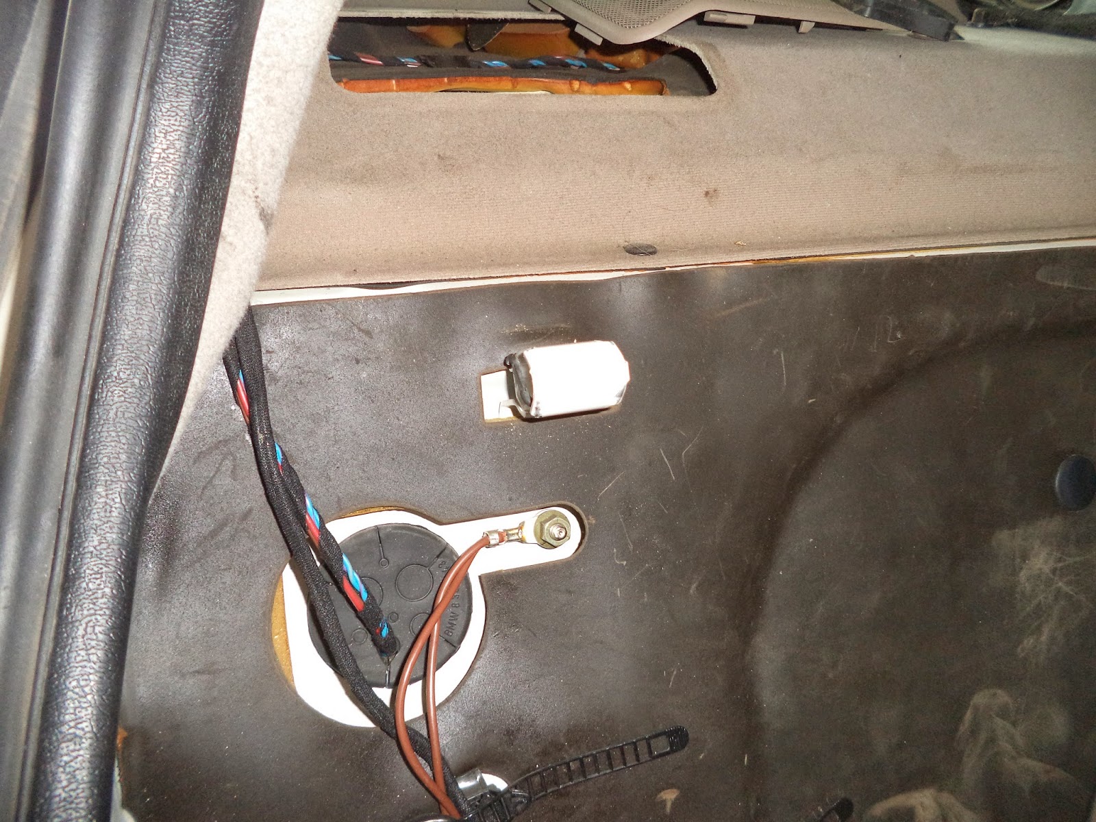
Picture DSC01582 showing the steel bracket (white plug shape in center of picture) that is welded to the rear bulkhead.  This view is on the passenger side.


Picture DSC01581 showing the corresponding socket  that is integral to the seat. This socket snaps over the bracket shown in Picture DSC01582 above.


Picture DSC01583 showing the welded steel slot (white rectangle slightly left of center) that is located at the rear of the seat.


Picture DSC01591 showing one of the two heavy steel pins (left and copper colored) and one of the two light duty steel pins (far right at the corner) that are integral to the seat.  The heavy duty pin slides into the socket shown in Picture DSC01583 above.

Since many of the electrical systems within the cabin had been disconnected, removing the rear seat required some thought as the rear doors were locked and the headrests were in the way.  By reclining the front seats full backwards it was possible to slide the back seat forward and then out of the car.  The doors were apparently in "child proof" mode as neither the buttons nor the door handles would open the doors.  Later it was finally remembered that when the 12 volt car battery is turned on, then the driver's door key will open all of the locks at the same time!


Picture DSC01285 showing the removal of the top portion of the rear seat.


Picture DSC01592 showing the rear view of the back seat after it was removed from the car.